
Hole forming method for cast-in-situ bored pile

A technology for drilling cast-in-place piles and hole forming, which is applied in drilling equipment and methods, drilling equipment, directional drilling, etc., can solve problems such as large safety risks, large limitations, and reduced hole forming efficiency.

Inactive Publication Date: 2020-07-07
GUANGDONG PROVINCIAL CHANGDA HIGHWAY ENG
View PDF10 Cites 10 Cited by
  • Summary
  • Abstract
  • Description
  • Claims
  • Application Information

AI Technical Summary

Problems solved by technology

[0004] 1. Rotary drilling is suitable for soft bedrock geology, especially for the construction of friction piles or end-bearing friction piles with a pile length of more than 100m, but the construction efficiency is low and the cost is relatively high;
[0005] 2. Percussion drilling is applicable to a wide range of geological conditions. When the depth of the pile hole is within 70m, its hole-forming efficiency is higher than that of rotary drilling. Pore ​​forming efficiency will be greatly reduced;
[0006] 3. Manual digging is suitable for pile foundation construction with good geological conditions and lower groundwater level. When encountering rocks, blasting can be used to assist construction. However, blasting construction needs to be far away from villages, highways and other areas with frequent population flows, which has relatively large limitations. Under normal circumstances, the depth of excavation should not exceed 20m, and the construction efficiency is low, and the safety risk is relatively large

Method used


Image

  • Hole forming method for cast-in-situ bored pile
  • Hole forming method for cast-in-situ bored pile
  • Hole forming method for cast-in-situ bored pile

Examples


Embodiment Construction

[0045] The following will clearly and completely describe the technical solutions in the embodiments of the present invention with reference to the accompanying drawings in the embodiments of the present invention. Obviously, the described embodiments are only some, not all, embodiments of the present invention. Based on the embodiments of the present invention, all other embodiments obtained by persons of ordinary skill in the art without creative efforts fall within the protection scope of the present invention.

[0046] It should be understood that the terms "first", "second", etc. are used in the present invention to describe various information, but these information should not be limited to these terms, and these terms are only used to distinguish information of the same type from each other. For example, "first" information may also be referred to as "second" information without departing from the scope of the present invention, and similarly, "second" information may al...


PUM


Abstract

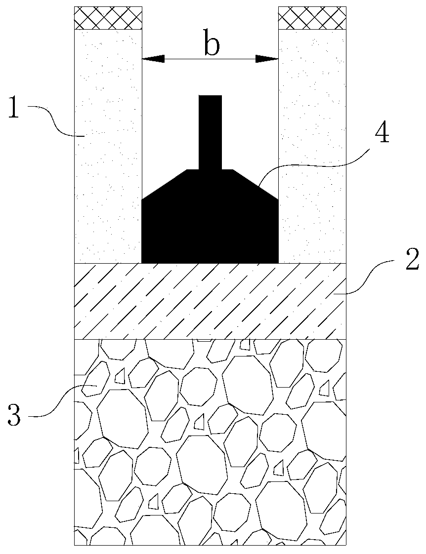
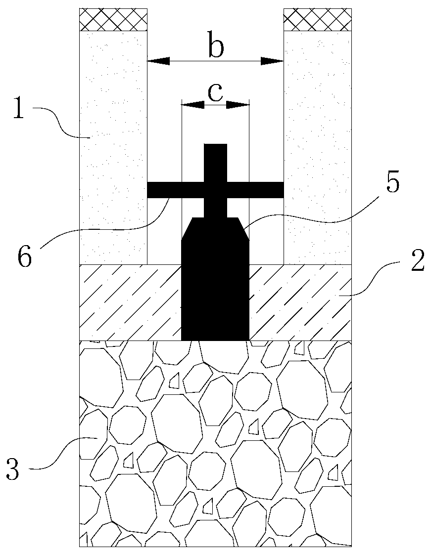
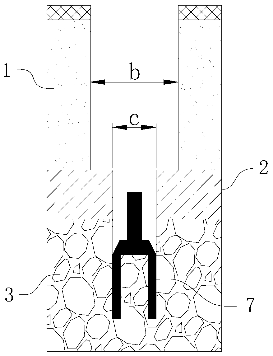
The invention relates to the technical field of bridge engineering, and discloses a hole forming method for a cast-in-situ bored pile. For a covering layer, a rotary drilling rig is assembled with a rotary drilling bucket for first drilling, and the construction efficiency is high; after entering rock, the rotary drilling rig is first assembled with a roller cone cylinder drill for secondary drilling, then a cutting pick cylinder drill is changed for third drilling, roller cone cylinder drills with different sizes are changed for step-by-step reaming, and at the stage, the problems of slow footage drilling, drill jamming, drill rod fracture and the like caused by insufficient torque after the rotary drilling rig enters the rock can be avoided; and after the reaming is in place, a percussion drill is changed to trim the hole shape of a primary pile hole, finally a mud circulating system is utilized to clear the formed pile hole, and it is ensured that the drilling slag at the bottom ofthe pile hole is thoroughly removed. Based on this, the hole forming method makes full use of the advantages of high hole forming efficiency of the rotary drilling rig, also makes up for the disadvantages of incomplete hole clearing of the rotary drilling rig, and has the advantages of high efficiency, low cost, small limitation, low safety risk, good hole forming quality and the like.

Description

technical field [0001] The invention relates to the technical field of bridge engineering, in particular to a hole-forming method for bored piles. Background technique [0002] With the rapid development of bridge construction in our country, the span of newly built bridges is getting larger and larger, and the structure is becoming more and more complex. At the same time, the design diameter of pile foundations is also getting larger and longer. The rock-socketed depth is getting deeper and deeper. Therefore, the construction technology of the pile foundation must be continuously updated and improved in order to meet the high requirements of new bridges and ensure the steady development of bridge construction in our country. [0003] Among the construction techniques of the pile foundation, the hole forming process is the most critical, which not only affects the progress and duration of the entire project, but also directly relates to the quality of the pile foundation. ...

Claims


Application Information

Patent Timeline
IPC IPC(8): E21B7/00E21B7/28E21B7/20E21B7/04E21B47/00
CPCE21B7/00E21B7/04E21B7/20E21B7/28E21B47/00
Inventor 杨勇詹元林彭昆杨斌财刘永杰谢朝君
Owner GUANGDONG PROVINCIAL CHANGDA HIGHWAY ENG
Learn More