
A method of using a self-locking nut

A self-locking nut and nut body technology, which is applied to nuts, screws, bolts, etc., can solve the problems of high product maintenance costs, interference damage, and failure to meet the locking performance requirements, and solve the problem of large attenuation of locking performance and lower cost effect

Active Publication Date: 2022-04-19
GUIZHOU AEROSPACE PRECISION PRODS
View PDF9 Cites 0 Cited by
  • Summary
  • Abstract
  • Description
  • Claims
  • Application Information

AI Technical Summary

Problems solved by technology

[0002] When using nuts and bolts for connection, when the components connected by the two are in a static environment, in order to prevent the nuts from loosening from the bolts, use elastic gaskets; but for dynamic environments with vibration, use elastic gaskets. The gasket can not prevent the nut from loosening. Self-locking nuts are required. By adopting rigid closure, even if the inner thread deforms and closely contacts the outer thread of the bolt to form interference, the purpose of anti-loosening and locking can be achieved; however, sometimes it is used After the self-locking nut is closed, due to equipment maintenance or dislocation of self-locking nut assembly, etc., it is necessary to take out and reinstall the self-locking nut, because after the self-locking nut is closed for the first time, the locking performance of the second use after disassembly is greatly reduced , cannot meet the locking performance requirements. After the first assembly, the threads of the bolts are seriously damaged due to interference during assembly and cannot be used again. Therefore, the bolts and nuts are used in pairs for one-time use and the maintenance cost of the product is high.

Method used


Image

  • A method of using a self-locking nut
  • A method of using a self-locking nut
  • A method of using a self-locking nut

Examples


Embodiment Construction

[0033] The technical solution of the present invention is further described below, but the scope of protection is not limited to the description.

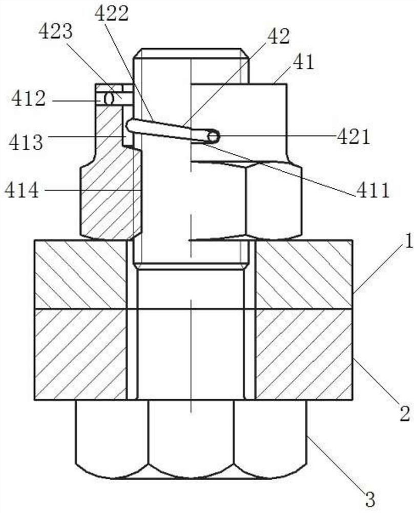
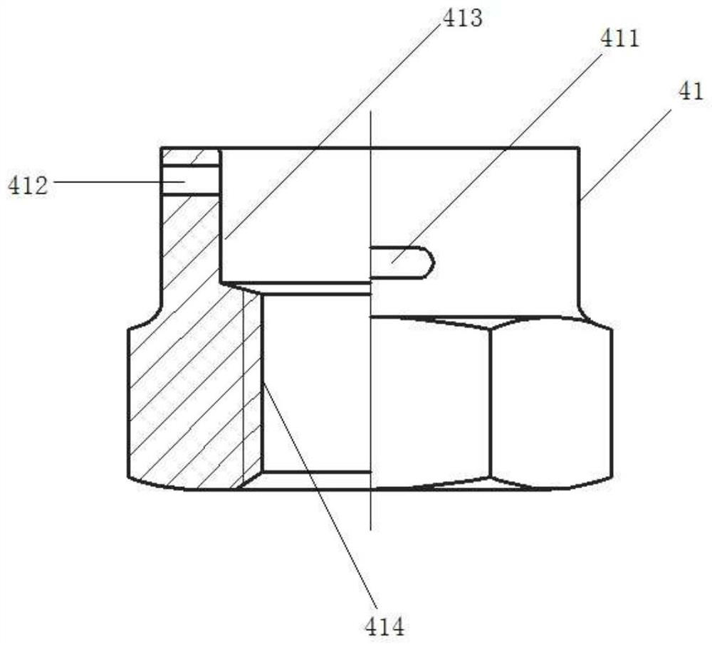
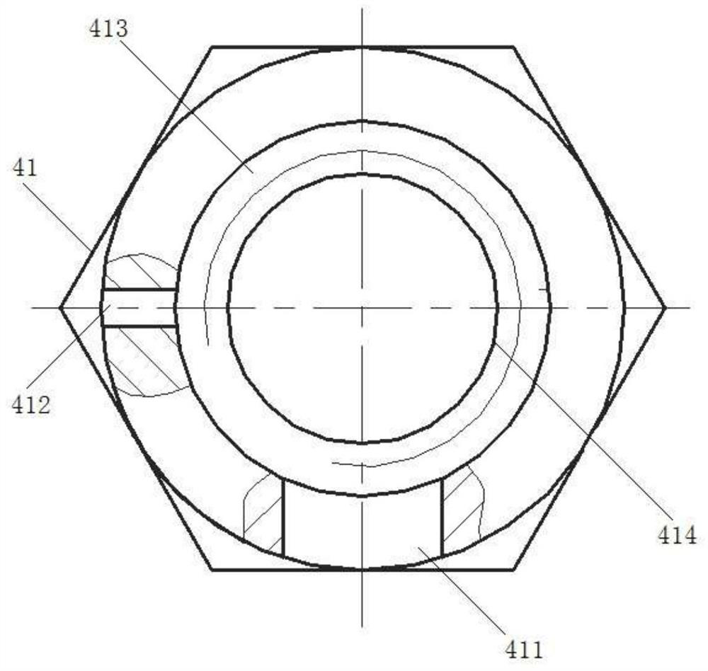
[0034] see Figure 1 to Figure 6 shown.

[0035] A kind of self-locking nut of the present invention, wherein, comprises: lock spring body 42 and nut body 41, and lock spring body 42 is installed in the nut body 41;

[0036] The lock spring body 42 includes a clamping end A421, a helical section 422, and a clamping end B423, and the clamping end A421 and the clamping end B423 are respectively fixedly connected to two ends of the helical section 422;

[0037] The nut body 41 is provided with an upper hole 413 and an internally screwed hole 414. The diameter of the upper hole 413 is larger than the inner screw hole 414. After the upper hole 413 is communicated with the internally screwed hole 414, the nut body 41 is formed to be able to penetrate and screw together. through holes for bolts;

[0038] The pitch of the helical segmen...


PUM


Abstract

According to a method for using a self-locking nut disclosed by the present invention, the lock spring body is installed in the nut body; The inner diameter of the lock spring body and the inner threaded hole of the nut body are screwed tightly with the outer thread of the bolt. At this time, the lock spring body has elastic potential energy; when the connector and the connector vibrate between each other, the lock spring The body relies on its own elastic potential energy to bring the nut body to tightly twist and hug the bolt to cooperate with constant locking, which avoids the loosening of the connection between the nut body and the bolt, and solves the problem of loosening and falling off of the connection between the nut body and the bolt in a dynamic environment of vibration; the lock The internally threaded holes of the spring body and the nut body are loosened and separated from the bolts; the lock spring body is screwed and separated from the bolts, and the lock spring body itself has no friction damage, which solves the problem of self-locking of the nut and the bolt to the bolt by the traditional rigid closing. The damage problem makes the locking performance of the lock spring body not attenuated after repeated disassembly and use.

Description

technical field [0001] The invention belongs to the field of connecting fasteners and relates to a method for using a self-locking nut. Background technique [0002] When using nuts and bolts for connection, when the components connected by the two are in a static environment, in order to prevent the nuts from loosening from the bolts, use elastic gaskets; but for dynamic environments with vibration, use elastic gaskets. The gasket can not prevent the nut from loosening. Self-locking nuts are required. By adopting rigid closure, even if the inner thread deforms and closely contacts the outer thread of the bolt to form interference, the purpose of anti-loosening and locking can be achieved; however, sometimes it is used After the self-locking nut is closed, due to equipment maintenance or dislocation of self-locking nut assembly, etc., it is necessary to take out and reinstall the self-locking nut, because after the self-locking nut is closed for the first time, the locking p...

Claims


Application Information

Patent Timeline
Patent Type & Authority Patents(China)
IPC IPC(8): F16B39/24F16B37/00
CPCF16B39/24F16B37/00
Inventor 赵惠光张红艳张明蕾许大伟李博
Owner GUIZHOU AEROSPACE PRECISION PRODS
Learn More