Damping mechanism with adjustable damping coefficient

A technology of damping coefficient and buffer mechanism, applied in mechanical equipment, springs, shock absorbers, etc., can solve the problems of complex shock absorbers, transformation, etc.

Inactive Publication Date: 2020-07-07
天津市垠昊鑫科技发展有限公司
View PDF0 Cites 0 Cited by
  • Summary
  • Abstract
  • Description
  • Claims
  • Application Information

AI Technical Summary

Problems solved by technology

However, the buffer mechanism on the market can only achieve one damping coefficient, which cannot be changed with use, and it is more complicated to replace the automobile shock absorber.

Method used


Image

  • Damping mechanism with adjustable damping coefficient

Examples


Embodiment Construction

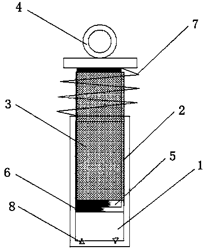
[0013] Now in conjunction with the accompanying drawings, the structure and use of the present invention will be further described. As shown in the figure, the invention includes 1. oil storage tank, 2. connecting rod, 3. rotating shaft, 4. rotating head, 5. first piston, 6. second piston, 7. elastic member, 8. one-way valve. Its specific structure is a buffer mechanism with an adjustable damping coefficient, including an oil storage tank, a connecting rod and a piston. The piston is provided with a hole that allows the liquid in the oil storage tank to circulate. The connecting rod is a hollow structure. The inside of the connecting rod is provided with a rotating shaft, the rotating shaft passes through the connecting rod and extends out of the connecting rod at both ends, the end of the rotating shaft protruding from the oil storage tank is movably connected to the first piston, and the end of the connecting rod A second piston is fixedly provided.

[0014] The end of the...


PUM


Abstract

A damping mechanism with adjustable damping coefficient comprises an oil storage tank, a connecting rod and pistons. Holes for enabling liquid in the oil storage tank to circulate are formed in the pistons. The connecting rod is of a hollow structure, a rotating shaft is arranged inside the connecting rod and penetrates the connecting rod, and two ends extend out of the connecting rod. The first piston is movably connected to one end, extending out of the oil storage tank, of the rotating shaft, and the second piston is fixed at the end of the connecting rod. Size of the holes in the pistons can be adjusted by rotating the relative position of the first piston to the second piston, the speed of liquid flow in the oil storage tank to penetrate the holes in the pistons is adjusted, so that the damping coefficient of the buffer mechanism is controlled, and the damping coefficient of a damper is adjusted.

Description

technical field [0001] The present disclosure generally relates to the production field of shock absorbers, and relates to a buffer mechanism with adjustable damping coefficient. Background technique [0002] The shock absorber on the car is required to be able to compress immediately when it encounters a bumpy road surface, and the shock absorber cannot be allowed to do a strong damping vibration after passing through, so the shock absorber must be designed to be easy to compress and rebound slowly , it is necessary to install a buffer mechanism on the shock absorber. The common buffer mechanism on the market uses the retardation and energy absorption of the oil to slow down the potential energy of the spring, and allows the oil to quickly flow out to the upper part of the piston and the interlayer during compression. In the middle, the compression speed of the shock absorber is fast; the slower it is to let the oil flow back from the upper part of the piston and the interl...

Claims


Application Information

Patent Timeline
Patent Type & Authority Applications(China)
IPC IPC(8): F16F9/19F16F9/32F16F9/34
CPCF16F9/19F16F9/3214F16F9/3405
Inventor 赵志军
Owner 天津市垠昊鑫科技发展有限公司
Why Eureka
Try Eureka