
Pile driving hammer damping system and damping control method

A technology of shock absorption system and piling hammer, which is applied in the direction of sheet pile wall, building, foundation structure engineering, etc. It can solve the problems of inability to maintain good shock absorption effect, different impact force, and inability to achieve stable work, etc.

Inactive Publication Date: 2020-07-17
KEEN OFFSHORE ENG CO LTD
View PDF6 Cites 0 Cited by
  • Summary
  • Abstract
  • Description
  • Claims
  • Application Information

AI Technical Summary

Problems solved by technology

[0003] The purpose of the present invention is to propose a piling hammer damping system and a damping control method to solve the problem that the existing piling hammer damping device cannot work stably or maintain a relatively high level when the piling construction environment is different or the impact force is different. Technical issues for good shock absorption

Method used


Image

  • Pile driving hammer damping system and damping control method
  • Pile driving hammer damping system and damping control method
  • Pile driving hammer damping system and damping control method

Examples


Embodiment Construction

[0035] The following will clearly and completely describe the technical solutions in the embodiments of the present invention with reference to the accompanying drawings in the embodiments of the present invention. Obviously, the described embodiments are only part of the embodiments of the present invention, not all of them. Based on the embodiments of the present invention, all other embodiments obtained by persons of ordinary skill in the art without creative efforts fall within the protection scope of the present invention.

[0036] It should be noted that if there is a directional indication (such as up, down, left, right, front, back...) in the embodiment of the present invention, the directional indication is only used to explain the position in a certain posture (as shown in the accompanying drawing). If the specific posture changes, the directional indication will also change accordingly.

[0037] In addition, if there are descriptions involving "first", "second" and ...


PUM


Abstract

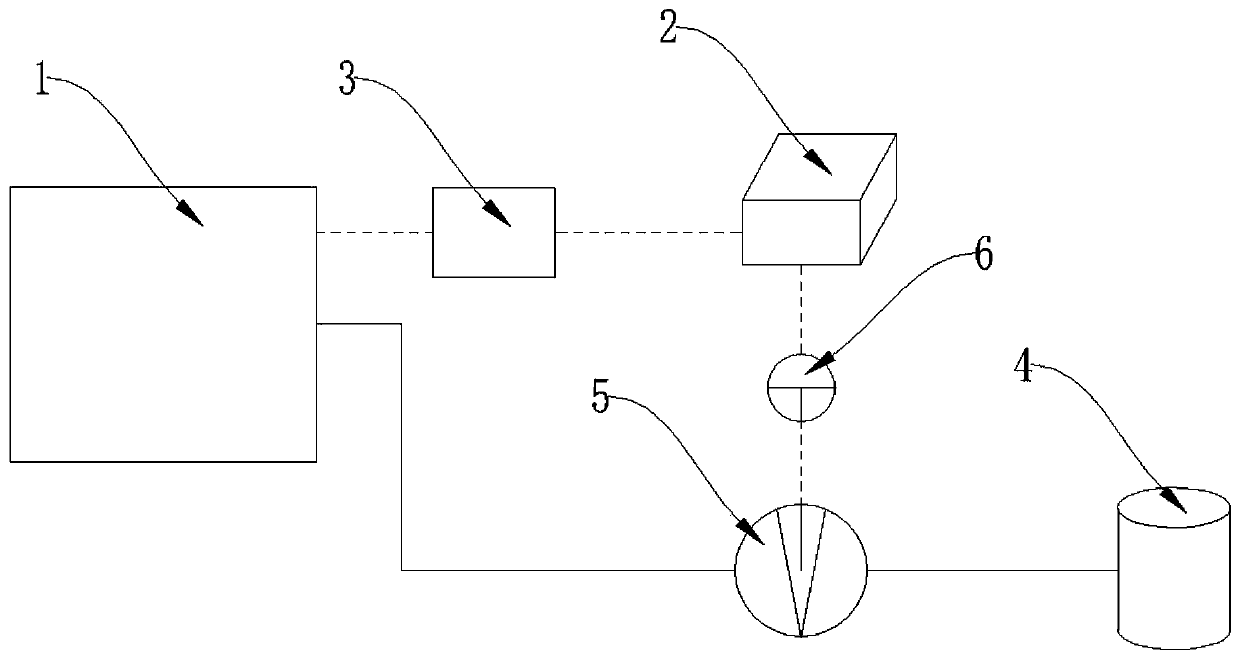
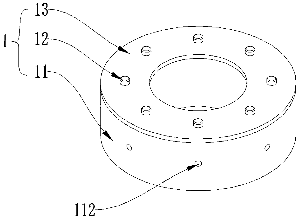
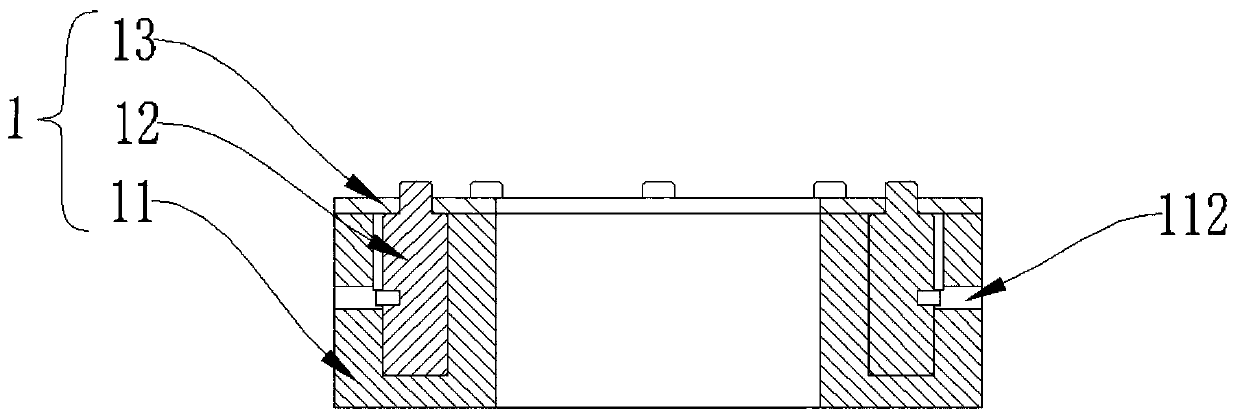
The invention provides a pile driving hammer damping system, comprising a damping device, a PLC, a hydraulic sensor, an oil tank, an oil pump, an oil pump controller, a hammer base and a helmet. The damping device is arranged in the hammer base, the damping device and the hammer base are arranged on the helmet in a sleeving mode, one end of the oil pump is connected with the damping device througha pipeline, the other end of the oil pump is connected with the oil tank through a pipeline, the hydraulic sensor is used for detecting the oil pressure of the damping device, the PLC is used for receiving a detection value of the hydraulic sensor and emitting a signal to the oil pump controller according to the detection value, and the oil pump controller is used for receiving the signal emittedby the PLC and controlling operation of the oil pump to enable hydraulic oil to be sucked or pumped into the oil pump to adjust the oil pressure of the damping device. According to the pile driving hammer damping system and a damping control method, the damping coefficient of the damping device can be adjusted in time to ensure that when the damping device is applied to different construction environments or striking force intensities are different, the damping device can keep a good damping effect.

Description

technical field [0001] The invention relates to the field of damping technology, in particular to a damping system and a damping control method for a piling hammer. Background technique [0002] Sea transport ships are constantly developing in the direction of large-scale. In order to meet the berthing and loading and unloading of large ships, the tonnage of newly-built wharves continues to increase. In the process of piling, alternate driving is often used so that it can act as a buffer between the piling hammer and the pile. During the piling process, the pile hammer hits the pile driver, and then hits the pile leg, and the pile leg will rebound upwards. Therefore, it is necessary to install a shock absorber to reduce the rebound force from the pile leg and reduce the adverse effects caused by system vibration. . Although the original damping device of piling hammer can effectively offset the rebound force of part of the pile legs, but when the piling construction enviro...

Claims


Application Information

Patent Timeline
Patent Type & Authority Applications(China)
IPC IPC(8): E02D7/10
CPCE02D7/10
Inventor 陆军李光远吴平平张静波马振军邓达纮麦志辉陈峰徐天殷张帅君
Owner KEEN OFFSHORE ENG CO LTD
Learn More