Plate-like member vibration control device

A vibration damping device and component technology, applied in the direction of shock absorbers, spring/shock absorber design features, spring/shock absorber functional characteristics, etc., can solve problems such as noise and vibration amplification

Active Publication Date: 2020-07-07
HONDA MOTOR CO LTD
View PDF6 Cites 2 Cited by
  • Summary
  • Abstract
  • Description
  • Claims
  • Application Information

AI Technical Summary

Problems solved by technology

[0007] In order for the piezoelectric element actuator to exert the vibration damping effect, it is necessary to set the feedback gain to be larger than 0 dB, but as explained in the section of the specific embodiment, there is the following problem: if the vibration damping amount is further obtained If the feedback gain is set large, the vibration will be amplified in the frequency range below 100Hz to generate noise

Method used


Image

  • Plate-like member vibration control device
  • Plate-like member vibration control device
  • Plate-like member vibration control device

Examples


no. 1 Embodiment approach

[0035] Below, based on Figure 1 to Figure 7 The first embodiment of the present invention will be described.

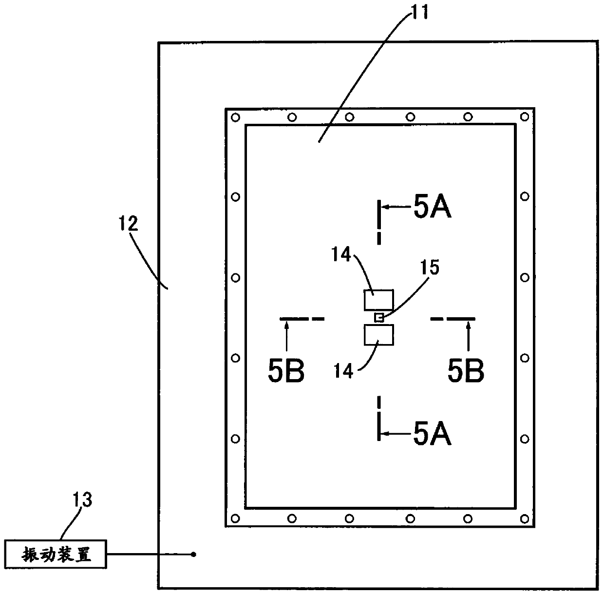
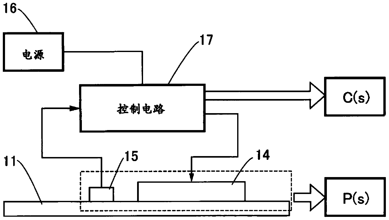
[0036] Such as figure 1 as well as figure 2 As shown, the plate-shaped member 11 to which the vibration damping device of the present invention is applied is composed of a rectangular plate made of carbon fiber reinforced resin, and the metal frame 12 supports the outer periphery of the plate-shaped member through a sufficiently lower elastic material. The metal frame 12 is connected to a vibrating device 13 to vibrate at various frequencies. The damping device for damping the vibration of the plate member 11 vibrated by the vibrating device 13 has: two piezoelectric element actuators 14 in the shape of a rectangular plate; a piezoelectric element sensor 15 in the shape of a rectangular plate; a power source 16; and The control circuit 17 controls the operation of the piezoelectric element actuator 14 based on the output of the piezoelectric element sensor 15 . ...

no. 2 Embodiment approach

[0061] Next, based on Figure 8 A second embodiment of the present invention will be described.

[0062] The vibration damping device of the first embodiment has two piezoelectric element actuators 14 and one piezoelectric element sensor 15, but the vibration damping device of the second embodiment has four piezoelectric element actuators 14 and four piezoelectric element Element sensor 15. At positions sandwiched by four piezoelectric element actuators 14 each formed in a rectangular shape, four piezoelectric element sensors 15 each formed in a strip shape are arranged in a cross shape. In series, in parallel, or in series combination (for example, after connecting two in parallel, connect the remaining two in series.) Electrically connect. In addition, the lengths of the four piezoelectric element sensors 15 are set so that anti-resonance can occur in the output voltage of the four piezoelectric element sensors 15 as a whole in the frequency range of 100 Hz or less.

[00...


PUM


Abstract

The invention provides a plate-like member vibration control device comprising piezoelectric element actuators, piezoelectric element sensors and a control circuit. The device can prevent the increaseof vibration within the range where the vibration frequency is below a predetermined value, increase the feedback gain, and reduce the noise caused by suppressing vibration. The vibration control device of a plate-like member 11 includes: a plurality of piezoelectric element actuators 14; at least one piezoelectric element sensor 15; and a control circuit 17 that performs feedback control of operation of the piezoelectric element actuators 14 based on an output voltage of the piezoelectric element sensor 15 so as to suppress vibration of the plate-like member 11. A layout of the piezoelectricelement sensor 15 and the piezoelectric element actuators 14 is set such that anti-resonance occurs in an output voltage of the piezoelectric element sensor 15 in a range where the vibration frequency of the plate-like member 11 is equal to or less than a predetermined value. Therefore, generation of noise can be prevented at the frequency. As a result, a gain can be increased at a control targetfrequency. Therefore, vibration can be suppressed, and noise can be reduced.

Description

technical field [0001] The present invention relates to a vibration damping device for a plate-like member, comprising: a plurality of piezoelectric element actuators arranged on the surface of the plate-like member; at least one piezoelectric element sensor positioned at a position; and a control circuit for feedback-controlling operations of the plurality of piezoelectric element actuators based on an output voltage of the piezoelectric element sensor in order to suppress vibration of the plate member. Background technique [0002] A vibration damping device is known by the following Patent Document 1, in which a piezoelectric element sensor (a piezoelectric element for detection) and a piezoelectric element actuator (a piezoelectric element for vibration damping) are fixed to the peripheral wall surface of the damper of a suspension device of an automobile. Piezoelectric element), the piezoelectric element sensor detects its own deformation accompanying the vibration of t...

Claims


Application Information

Patent Timeline
Patent Type & Authority Applications(China)
IPC IPC(8): F16F15/00H02N2/00
CPCF16F15/002F16F15/005H02N2/008H02N2/005F16F2228/04F16F2230/08F16F2230/18B06B1/0253B06B2201/55G10K2210/1291G10K11/17857G10K11/17875F16F2224/0283B06B2201/30
Inventor 铃木俊次山口俊澄
Owner HONDA MOTOR CO LTD
Why Eureka
Try Eureka