Support structure of computer screen

A support structure, computer screen technology, applied in the direction of machine/stand, supporting machine, mechanical equipment, etc., can solve the problem of moving, removing the computer screen, and inconvenient for users to watch the computer screen.

Inactive Publication Date: 2020-07-07
漳州市杰成电子产品有限公司
View PDF8 Cites 0 Cited by
  • Summary
  • Abstract
  • Description
  • Claims
  • Application Information

AI Technical Summary

Problems solved by technology

[0003] But the existing computer screen bracket cannot move the position of the computer screen without moving the base, and the height of the computer screen is fixed. Occupies a larger position on the desk, and the computer screen cannot be easily removed through the stand when not using the computer, which is not conducive to office workers using the desk space

Method used


Image

  • Support structure of computer screen
  • Support structure of computer screen
  • Support structure of computer screen

Examples


Embodiment 1

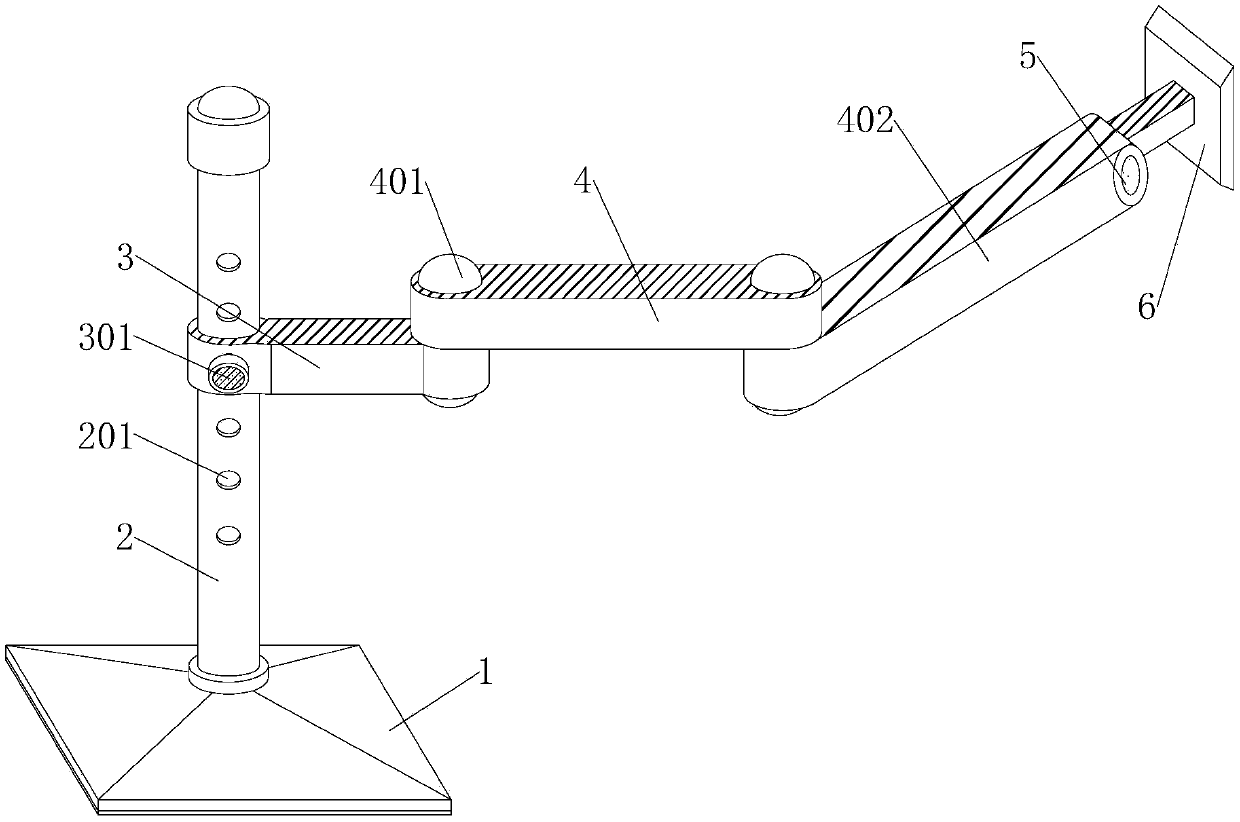
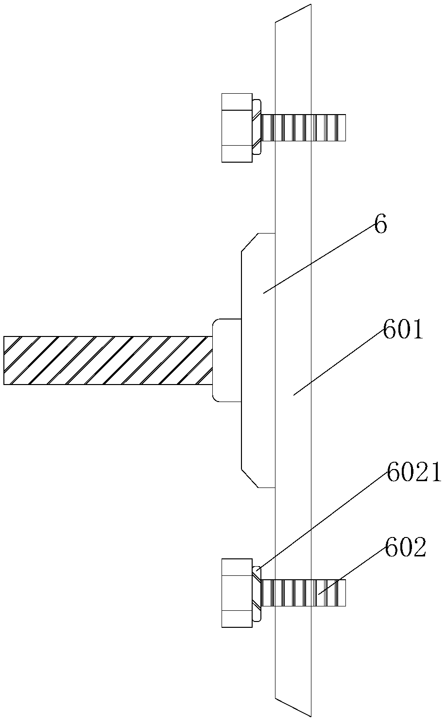
[0022] refer to Figure 1-3 , a bracket structure for a computer screen, comprising a base 1, a column 2, a main cantilever 3 and a fixed plate 6, a column 2 is fixedly connected to the middle position of the upper end surface of the base 1, and one end of the main cantilever 3 is clamped on the outer wall of the column 2. The other end of the cantilever 3 is rotatably connected with a damping shaft 401, and the upper outer wall of the damping shaft 401 is rotatably connected with one end of a primary connecting rod 4, and the other end of the primary connecting rod 4 is movably connected with a secondary connecting rod 402 through the damping rotating shaft 401. The end of the connecting rod 402 away from the damping shaft 401 is fixedly connected with the movable shaft 5, the outer wall of the movable shaft 5 is closely attached to the fixed plate 6, the front of the fixed plate 6 is welded with a connecting panel 601, and the front of the connecting panel 601 is connected wi...

Embodiment 2

[0024] refer to figure 1 and Figure 5 , a support structure of a computer screen, which is basically the same as that of Embodiment 1, furthermore, the bottom of the base 1 is fixedly connected with a base plate 101, the upper end surface of the base plate 101 is closely attached to a cover plate 103, and the column 2 passes through the cover plate 103 is fixedly connected with the bottom plate 101, the outer wall of the lower part of the column 2 is closely attached to the external convex thread 202, and the outer wall of the external convex thread 202 is rotatably connected to the fixed knob 102, and the fixed knob 102 is compatible with the external convex thread 202, and the bottom plate 101 passes through the The bolts are fixed to the desktop, and the cover plate 103 is close to the upper surface of the base plate 101, avoiding the exposure of the fixing bolts on the base plate 101, ensuring the appearance of the bracket, and by turning the fixing knob 102 that is compa...

Embodiment 3

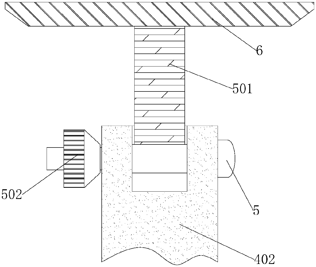
[0028] refer to Figure 2-4 , a support structure of a computer screen, which is basically the same as that of Embodiment 1. Further, the inner wall of the movable shaft 5 is rotatably connected to one end of a positioning column 501, and the other end of the positioning column 501 is fixedly connected to the fixed plate 6, and the movable shaft 5 runs through the secondary connecting rod 402, and the left outer wall of the movable rotating shaft 5 is sleeved with a movable nut 502, and the movable nut 502 is closely attached to the secondary connecting rod 402. When the movable nut 502 is tightened, the movable nut 502 and the movable rotating shaft 5 Compress the secondary connecting rod 402, so that the secondary connecting rod 402 is close to the positioning column 501, fix the positioning column 501 and the primary fixing plate 6, thereby fixing the computer screen, when the movable nut 502 is loosened, the positioning column 501 is on the movable shaft 5 Rotate upwards t...


PUM


Abstract

The invention discloses a support structure of a computer screen, and belongs to the field of screen supports. According to the technical scheme, the support structure is characterized by comprising abase, a stand column, a main cantilever and a fixing plate; the stand column is fixedly connected to the middle of the upper end face of the base; one end of the main cantilever is clamped to the outer wall of the stand column, and the other end of the main cantilever is rotationally connected with a damping rotating shaft; one end of a first-stage connecting rod is rotationally connected to theouter wall of the upper portion of the damping rotating shaft, and the other end of the first-stage connecting rod is movably connected with a second-stage connecting rod through another damping rotating shaft; and a movable rotating shaft is fixedly connected to the end, away from the damping rotating shaft, of the second-stage connecting rod. The main cantilever is fixed through limiting holes with different heights in the stand column, the height of the main cantilever can be conveniently adjusted, and therefore the height of the computer screen is adjusted, and a user can watch the computer screen conveniently; and the damping rotating shafts at the two ends of the first-stage connecting rod rotate, the second-stage connecting rod retracts to the stand column, the computer screen is far away from an office area on a desktop, and the situation that the computer screen still occupies too many desktop positions when not used is avoided.

Description

technical field [0001] The invention relates to the field of screen brackets, in particular to a computer screen bracket structure. Background technique [0002] At present, computer has become a kind of common tool, is widely used in many fields such as office, entertainment and scientific research, and computer screen is generally fixed on the desktop by the base that self carries, and base is close to desktop, and the computer screen is fixed on the base on the top of the base. The computer screen can be fixed on the bracket, and the connection between the bracket and the computer screen is generally provided with a rotating mechanism, and the user can vertically rotate the computer in a small range, so that the user can watch the computer screen. [0003] But the existing computer screen bracket cannot move the position of the computer screen without moving the base, and the height of the computer screen is fixed. Occupies a larger position on the desk, and the computer...

Claims


Application Information

Patent Timeline
Patent Type & Authority Applications(China)
IPC IPC(8): F16M11/24F16M11/38F16M11/10F16M11/04F16M11/16
CPCF16M11/04F16M11/10F16M11/16F16M11/2014F16M11/24
Inventor 蔡钊培
Owner 漳州市杰成电子产品有限公司
Why Eureka
Try Eureka