A self-calibration method of laser displacement sensor

A laser displacement and laser sensor technology, applied in the field of laser calibration, can solve the problems of low self-calibration accuracy and low self-calibration efficiency, and achieve the effects of strong industrialization and automation capabilities, high precision and high efficiency

Active Publication Date: 2021-09-03
NINGBO DAZHENG IND ROBOT TECH CORP
View PDF0 Cites 0 Cited by
  • Summary
  • Abstract
  • Description
  • Claims
  • Application Information

AI Technical Summary

Problems solved by technology

[0003] The present invention aims to overcome the problems of low self-calibration accuracy and low self-calibration efficiency of the laser displacement sensor in the prior art, and provides a self-calibration method for the laser displacement sensor. This method uses the laser displacement sensor to illuminate and move the sensor Accurate laser tool coordinates, high precision, high efficiency and easy industrialization

Method used


Image

  • A self-calibration method of laser displacement sensor
  • A self-calibration method of laser displacement sensor

Examples


Embodiment

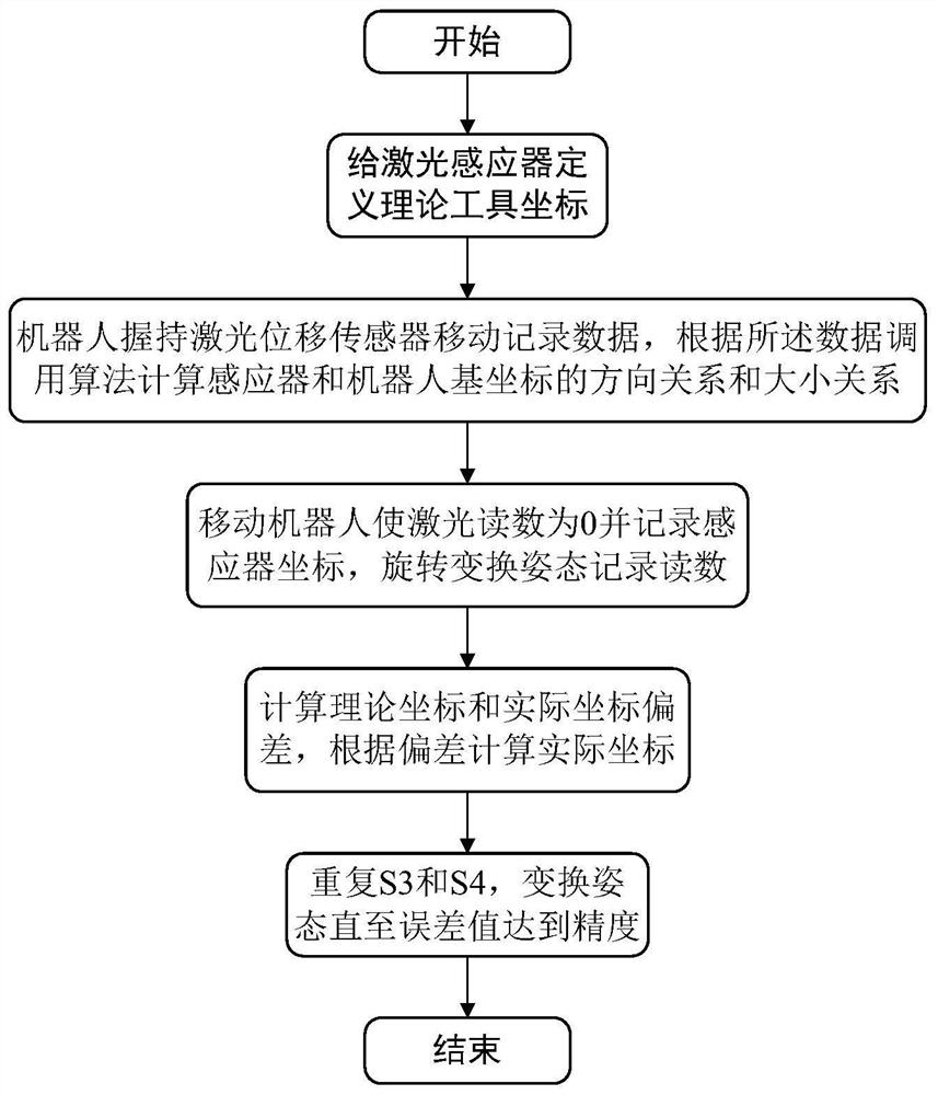
[0044] In this embodiment, a laser displacement sensor self-calibration method, such as figure 1 shown, including the following steps:

[0045] Step S1: define theoretical tool coordinates for the laser sensor;

[0046] Step S1 specifically includes the following steps:

[0047] S11: Take the position where the laser reading is 0 as the origin of the theoretical tool coordinates;

[0048] S12: Define the theoretical tool coordinates with the laser direction as the z-axis.

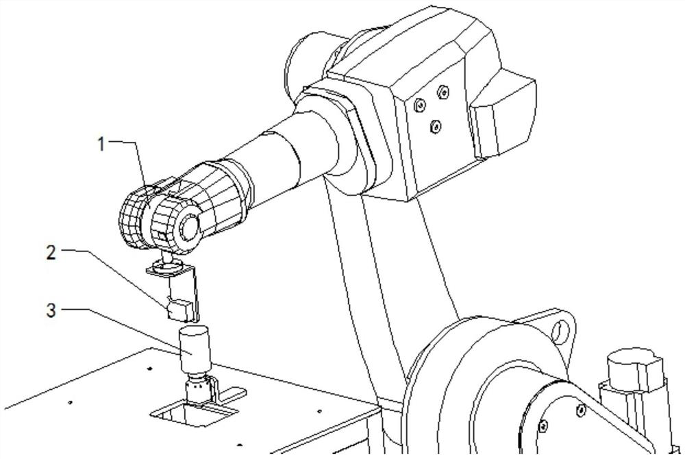
[0049] Step S2: The robot holds the laser displacement sensor to move and record data, and calls an algorithm to calculate the direction relationship and size relationship between the sensor and the robot base coordinates according to the data;

[0050] Step S2 specifically includes the following steps:

[0051] S21: The robot holds the laser displacement sensor and moves 5mm along the x-axis of the base coordinate;

[0052] S22: The robot holds the laser displacement sensor and moves 5mm along the y-a...


PUM


Abstract

The invention discloses a laser displacement sensor self-calibration method, which overcomes the problem of low laser calibration accuracy and low efficiency in the prior art. By defining theoretical tool coordinates for the laser sensor, the robot holds the laser displacement sensor to move and record data. According to the The data call algorithm calculates the direction relationship and size relationship between the sensor and the robot base coordinates; moves the robot so that the laser reading is 0 and records the sensor coordinates, and rotates and transforms the posture to record the readings; calculates the deviation between the theoretical coordinates and the actual coordinates, and calculates the actual coordinates according to the deviation; Transform poses repeatedly until the error value reaches precision. The present invention is based on the laser tool self-calibration technology of the industrial six-axis robot. Through the irradiation and movement of the sensor by the laser displacement sensor installed on the robot, the precise coordinates of the laser tool are calculated to achieve high precision, high efficiency, and automatic calibration. Effect.

Description

technical field [0001] The invention relates to the field of laser calibration, in particular to a laser displacement sensor self-calibration method with accurate calculation, high precision and high efficiency. Background technique [0002] With the rapid development of science and technology, lasers have vital uses in many fields, so laser automatic calibration, a technology with high precision requirements, is proposed. Laser calibration technology requires very high process precision, but due to various Due to various environmental or external factors, the accuracy of laser calibration needs to be improved. For example, traditional calibration generally uses measurement, three-point method, or direct use of model theoretical values. The accuracy depends on the human eye and tolerances. The calibration effect between the laser displacement sensor and the sensor is not good, so the efficiency is low and the accuracy is low. Contents of the invention [0003] The present...

Claims


Application Information

Patent Timeline
Patent Type & Authority Patents(China)
IPC IPC(8): G01B11/02G01B11/00
CPCG01B11/002G01B11/02
Inventor 戴翔
Owner NINGBO DAZHENG IND ROBOT TECH CORP
Why Eureka
Try Eureka