Optical axis included angle measurement adjusting device

A technology for adjusting devices and measuring devices, which can be applied to measuring devices, optical devices, televisions, etc., and can solve problems such as inconvenience and low efficiency

Inactive Publication Date: 2020-07-07
SHENZHEN KUANG CHI METAMATERIAL TECH LTD
View PDF4 Cites 1 Cited by
  • Summary
  • Abstract
  • Description
  • Claims
  • Application Information

AI Technical Summary

Problems solved by technology

It can be seen that all of these, without exception, require the use of theodolite and other equip...

Method used


Image

  • Optical axis included angle measurement adjusting device
  • Optical axis included angle measurement adjusting device
  • Optical axis included angle measurement adjusting device

Examples


Embodiment 1

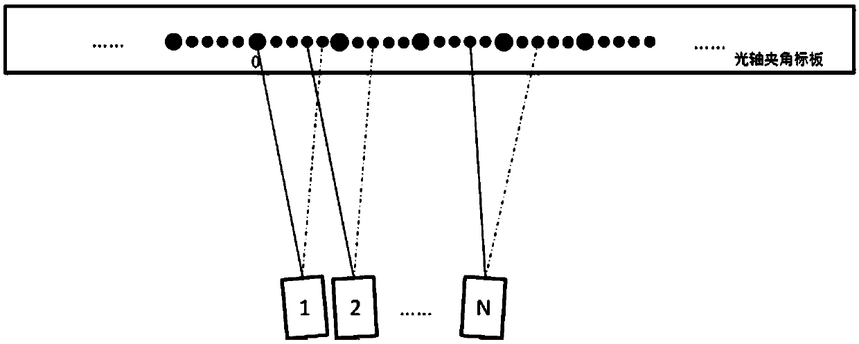
[0022] figure 1 It is an embodiment of the optical axis angle measurement and adjustment device of the present invention. Such as figure 1 As shown, what is proposed is a camera optical axis angle measurement device placed in the horizontal direction, and the positional relationship between the cameras is a left-right relationship. It includes cameras No. 1, No. 2...N installed with the optical axis angle to be measured and the optical axis angle measurement target plate. Cameras No. 1, No. 2...N are installed or assembled on the same height plane. The optical axis of the camera whose optical axis angle is to be measured faces the measurement target plate, and the measurement target plate is taken as the shooting target. The mounting bases of cameras 1 to N each have a mechanical structure for fine-tuning the angle, such as a universal joint, for calibration of the included angle of the optical axis. Camera real-time video can be electronically zoomed in. The distance bet...

Embodiment 2

[0066] Figure 4 It is another embodiment of the optical axis angle measurement and adjustment device of the present invention. This embodiment and figure 1 The difference is that the positional relationship of the camera group is an up-down relationship, and the optical axis angle measurement target is placed vertically. The optical axis angle measurement and adjustment process are the same as figure 1 Example.

[0067] Such as Figure 4 As shown, the optical axis angle measurement and adjustment device includes a camera for measuring the optical axis angle and a measurement target plate. Cameras No. 1, No. 2...N are placed vertically, and the positional relationship between the cameras is the online relationship. The optical axis angle measurement target plate is placed horizontally. Cameras No. 1, No. 2...N are installed or assembled on the same height plane. The optical axis of the camera whose optical axis angle is to be measured faces the measurement target plate,...


PUM


Abstract

The invention provides an optical axis included angle measurement adjusting device, which comprises at least two cameras and a measuring target plate, wherein the at least two cameras are mounted or assembled on the same height plane, and optical axes of the at least two cameras face the measuring target plate and form an included angle; the distance between the measuring target plate and the at least two cameras is L, the distance between intersection points of the optical axes of the at least two cameras and the measurement target plate is d, and the distance between the at least two camerasis D; and the optical axis included angle between the at least two cameras is expressed as shown in the description by radian. By using the included angle measuring target plate, the optical axis included angle relationship between the cameras can be conveniently and efficiently determined, and the camera groups in the up-and-down or left-and-right positional relationship can be easily measured.For cameras installed on universal joints and other devices, optical axis included angle real-time calibration can be carried out according to real-time video images.

Description

【Technical field】 [0001] The invention relates to the technical field of angle measurement, in particular to an optical axis angle measurement and adjustment device. 【Background technique】 [0002] In a device that requires two or more cameras to work together, the determination of the angle between the optical axes is very important. It involves image center point offset, image overlapping area calibration and panorama stitching, etc. In the prior art, the angle of the optical axis is determined by means of theodolite, reading microscope and other equipment; or by taking pictures, the actual object distance and the coordinate value of the image plane are correspondingly deduced to deduce the angle of the optical axis; or by taking pictures, post-processing to obtain the angle of the optical axis. It can be seen that all of these, without exception, require the use of theodolite and other equipment to perform complex post-calculation on the captured pictures, so it is inco...

Claims


Application Information

Patent Timeline
IPC IPC(8): H04N17/00H04N5/232H04N5/247
CPCH04N17/002H04N23/60H04N23/90H04N17/00G01B11/26
Inventor 刘若鹏栾琳张旋
Owner SHENZHEN KUANG CHI METAMATERIAL TECH LTD
Why Eureka
Try Eureka