Supercharge Your Innovation With Domain-Expert AI Agents!

A cooling device for an electrical control device

A technology for electrical control devices and heat dissipation devices, which is applied in the direction of electrical components, structural parts of electrical equipment, cooling/ventilation/heating transformation, etc. The effect of service life and drive stability

Active Publication Date: 2021-11-09
新疆轻工职业技术学院
View PDF0 Cites 0 Cited by
  • Summary
  • Abstract
  • Description
  • Claims
  • Application Information

AI Technical Summary

Problems solved by technology

[0005] In view of this, the object of the present invention is to provide a heat dissipation device for an electrical control device to solve the problem that the existing filter screen structure is easy to block and difficult to disassemble, which is proposed in the above-mentioned background technology

Method used


Image

  • A cooling device for an electrical control device
  • A cooling device for an electrical control device
  • A cooling device for an electrical control device

Examples


Embodiment Construction

[0041] The following will clearly and completely describe the technical solutions in the embodiments of the present invention with reference to the accompanying drawings in the embodiments of the present invention. Obviously, the described embodiments are only some, not all, embodiments of the present invention. Based on the embodiments of the present invention, all other embodiments obtained by persons of ordinary skill in the art without making creative efforts belong to the protection scope of the present invention.

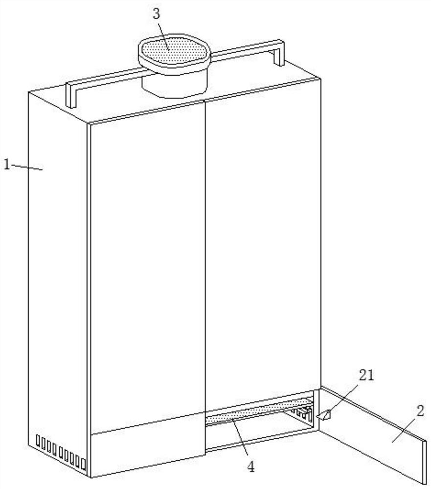
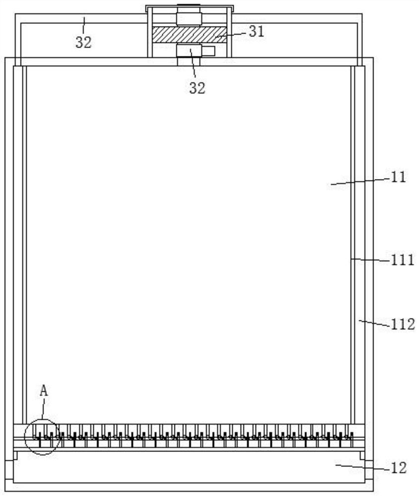
[0042] The invention provides a heat dissipation device for an electrical control device. For its specific structure, please refer to Figure 1-Figure 12 Shown:

[0043] First describe the main structure:

[0044] Including the cabinet body 1 and the fan assembly 3 installed on the top of the cabinet body 1, an upper cavity 11 and a lower cavity 12 are formed in the cabinet body 1 from top to bottom, and the upper cavity 11 and the lower cavity 12 are respectiv...


PUM


Abstract

The invention belongs to the technical field of heat dissipation of electric devices, and discloses a heat dissipation device of an electric control device, which includes a cabinet body and a fan assembly installed on the top of the cabinet body. An upper chamber and a lower chamber are sequentially formed in the cabinet body from top to bottom. In addition, the upper chamber and the lower chamber are respectively equipped with independent cabinet doors, and the two sides of the lower chamber are symmetrically provided with heat dissipation holes; the air filter assembly is installed in the lower chamber, and the air filter assembly includes fixed ones arranged in sequence from top to bottom. Porous bottom plate, lifting filter screen and rotary swing assembly; in the present invention, a movable filter screen and a fixed porous bottom plate are arranged together: when the filter screen is limited to the highest level, the conduction between the filter screen and the porous plate is realized, In order to realize the rapid heat dissipation operation of the upward flow of air flow; when the filter screen is limited to the lowest level, the porous bottom plate is closed, and at the same time cooperate with the cooling chamber to realize the heat dissipation of the air flow downward and the backwashing operation of the filter screen; in summary, the filter screen is not disassembled The reverse cleaning of the filter can be realized by pressing down.

Description

technical field [0001] The invention belongs to the technical field of heat dissipation of electric devices, and in particular relates to a heat dissipation device of an electric control device. Background technique [0002] Electrical control devices mainly refer to electrical control cabinets, which are used to install various electrical components as terminal equipment for controlling the use of electrical energy. In actual use, due to the heat generation and heat dissipation generated by the electrical components during operation, the temperature in the overall electrical control device will gradually increase, which in turn will affect the service life of the electrical components. high. [0003] Based on the above problems, the prior art mainly includes heat dissipation methods such as wind circulation and water circulation. Taking wind circulation as an example, the principle is to increase the air circulation speed in the electrical control device to accelerate the ...

Claims


Application Information

Patent Timeline
Patent Type & Authority Patents(China)
IPC IPC(8): H05K7/20
CPCH05K7/20572
Inventor 关艳翠杨振元陈文涛赵硕伟多里坤·艾克白尔樊春年关鹏羽王俊娜
Owner 新疆轻工职业技术学院
Features
  • R&D
  • Intellectual Property
  • Life Sciences
  • Materials
  • Tech Scout
  • Unparalleled Data Quality
  • Higher Quality Content
  • 60% Fewer Hallucinations
Learn More