
Head traction support device

A technology for supporting device and head, applied in the field of medical surgery, can solve problems such as difficulty in supporting the lower forehead and face, and achieve the effects of accurate traction weight, convenient angle adjustment, and avoidance of pressure injury

Active Publication Date: 2020-07-10
FIRST HOSPITAL AFFILIATED TO GENERAL HOSPITAL OF PLA
View PDF11 Cites 3 Cited by
  • Summary
  • Abstract
  • Description
  • Claims
  • Application Information

AI Technical Summary

Problems solved by technology

For this reason, the embodiment of the present invention proposes a head traction support device to solve the problem that it is difficult to support the lower forehead and face if it is necessary to change from the supine position to the prone position when the traction bow is used during the operation.

Method used


Image

  • Head traction support device
  • Head traction support device
  • Head traction support device

Examples


Embodiment Construction

[0036] Embodiments of the present invention will be further described in detail below in conjunction with the accompanying drawings and examples. The following examples are used to illustrate the present invention, but should not be used to limit the scope of the present invention.

[0037] In the description of the embodiments of the present invention, it should be noted that the terms "center", "longitudinal", "transverse", "upper", "lower", "front", "rear", "left", "right" , "vertical", "horizontal", "top", "bottom", "inner", "outer" and other indicated orientations or positional relationships are based on the orientations or positional relationships shown in the drawings, and are only for the convenience of describing this The embodiments and simplified descriptions of the invention do not indicate or imply that the devices or elements referred to must have a specific orientation, be constructed and operate in a specific orientation, and thus should not be construed as lim...


PUM


Abstract

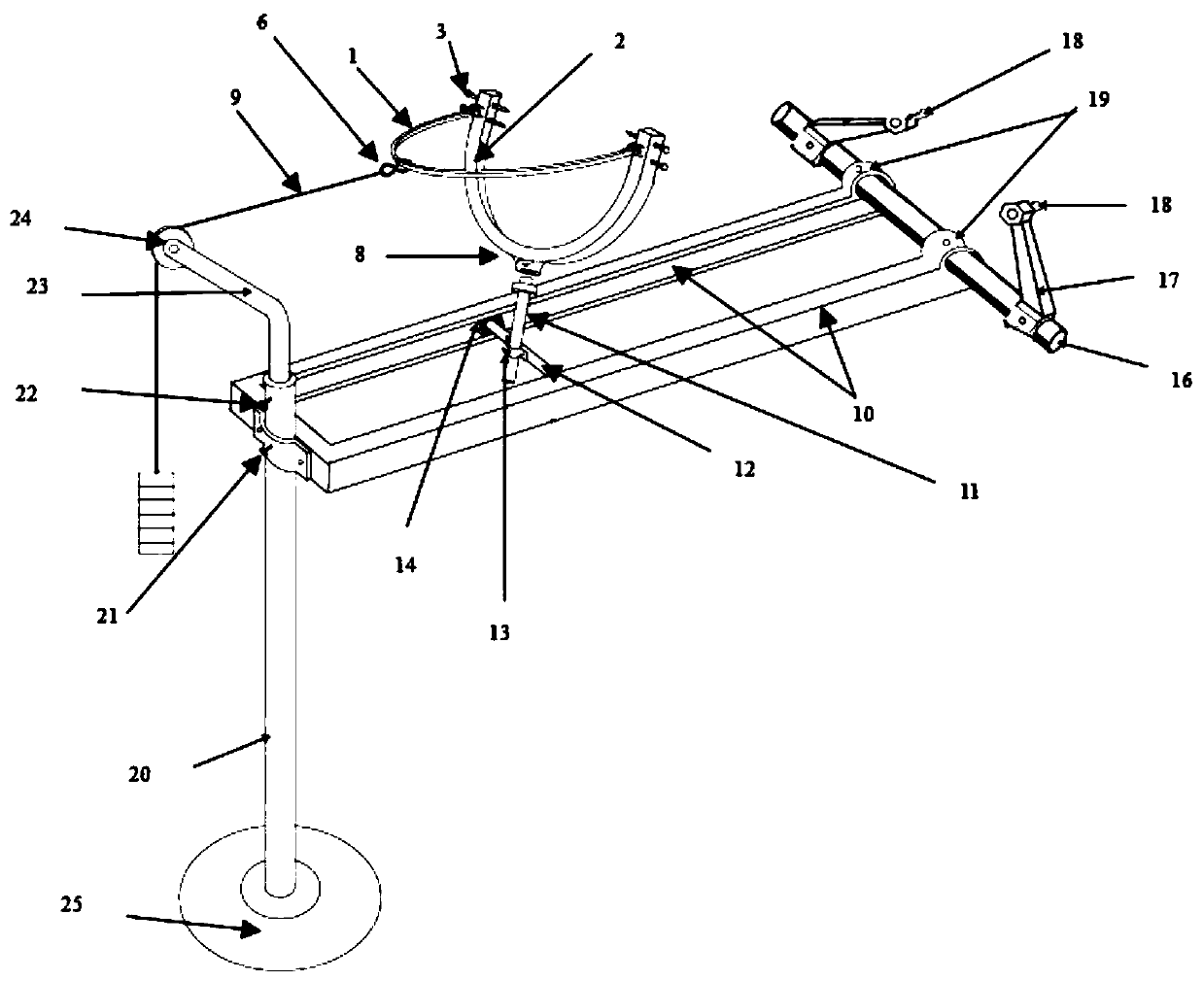
The invention relates to the field of medical surgery, and discloses a head traction support device. The device comprises a head frame, a traction bow, a pair of slide rails, a head frame support cross bar, a head frame supporting post, a pulley post, and a main cross bar, wherein the head frame is provided with a head frame support column interface, and skull positioning pieces are provided at both ends; the traction bow is hinged to both ends of the head frame; the pair of slide rails are oppositely arranged and provided with slide grooves, and one end of the pair of slide rails is connectedby a horizontal rail; two ends of the head frame support cross bar are respectively penetrated in the pair of slide rails; one end of the head frame support column is fixedly connected to the head frame support cross bar, and the other end is detachably connected to the head frame support column interface; a top end of the pulley post is provided with a pulley lifting rod, a top of the pulley lifting rod is provided with a fixed pulley, the traction bow passes around the fixed pulley through a traction rope, and an outer side of the horizontal rail can be lifted and fixed on the pulley post;the main cross bar passes through an end of the pair of slide rails away from the cross rail and is rotatably connected to the pair of slide rails, and main cross bar is located at an outer end of thepair of slide rails and is provided with an operating bed connecting arm. The device can traction and support the head reliably, and has accurate traction weight in a prone position and avoids facialand eye pressure injuries.

Description

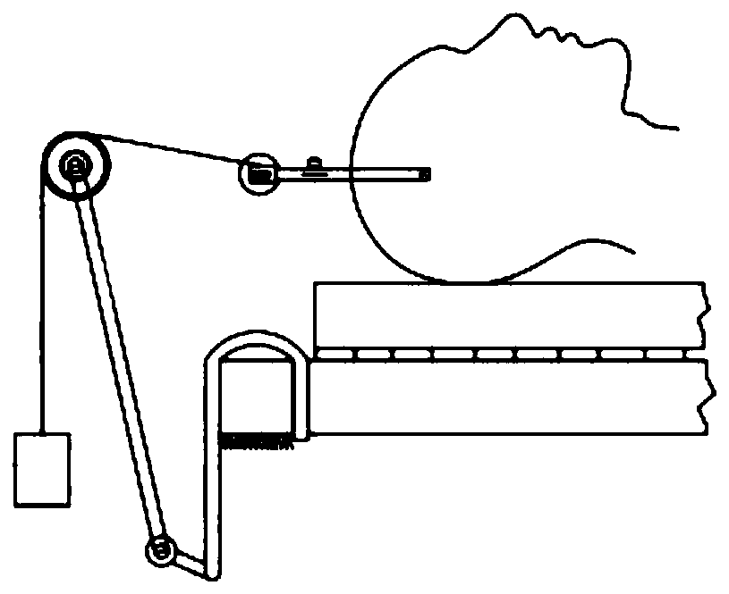
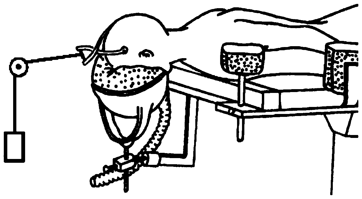
technical field [0001] The invention relates to the technical field of medical operations, in particular to a head traction support device. Background technique [0002] Surgery for craniocervical junction deformities often needs to be performed under skull traction, and in some cases it is necessary to change from the supine position to the prone position during the operation. The existing headgear is in a fixed form, and the traction is carried out with the head high and the feet low, and the weight of the body drooping. Existing cranial traction bow traction, such as figure 1 As shown, the pulley weight is used for traction, the traction weight is clear, and it is generally used for long-term traction in the ward. If it is necessary to change from the supine position to the prone position when the traction bow is used during the operation, such as figure 2 As shown, it is difficult to support the lower frontal face. If it slips off, there is a danger of crushing the e...

Claims


Application Information

Patent Timeline
Patent Type & Authority Applications(China)
IPC IPC(8): A61B17/66A61G13/12A61G13/10
CPCA61B17/66A61G13/121A61G13/10A61G13/126A61G13/1285A61B2017/564A61G2210/10
Inventor 闫润民姜红振苏新文吉慧军
Owner FIRST HOSPITAL AFFILIATED TO GENERAL HOSPITAL OF PLA
Learn More