
A steel structure construction solid waste recycling and processing equipment

A solid waste, recycling and processing technology, applied in construction waste recycling, solid waste removal, recycling technology and other directions, can solve problems such as uneven incision of protective layer, poor peeling effect of protective layer, and impact of protective layer recycling, etc. To achieve the effect of easy peeling action

Active Publication Date: 2021-04-30
赣州市束薪再生资源有限公司
View PDF13 Cites 0 Cited by
  • Summary
  • Abstract
  • Description
  • Claims
  • Application Information

AI Technical Summary

Problems solved by technology

[0004] 1. When the steel pipe protective layer is cut, the steel pipe protective layer cannot be completely separated due to uneven cutting force or certain deformation on the steel pipe surface. It is necessary to manually check the steel pipe protective layer. When the steel pipe protective layer is cut, the steel pipe will rotate, resulting in The cut of the protective layer is uneven, which affects the recycling of the protective layer;
[0005] 2. After the steel pipe protective layer is cut, it is necessary to manually turn the incision position of the protective layer outward. Manually turning the protective layer is more troublesome, resulting in poor peeling effect of the protective layer

Method used


Image

  • A steel structure construction solid waste recycling and processing equipment
  • A steel structure construction solid waste recycling and processing equipment
  • A steel structure construction solid waste recycling and processing equipment

Examples


Embodiment Construction

[0028] The embodiments of the present invention will be described in detail below with reference to the accompanying drawings, but the present invention can be implemented in many different ways defined and covered by the claims.

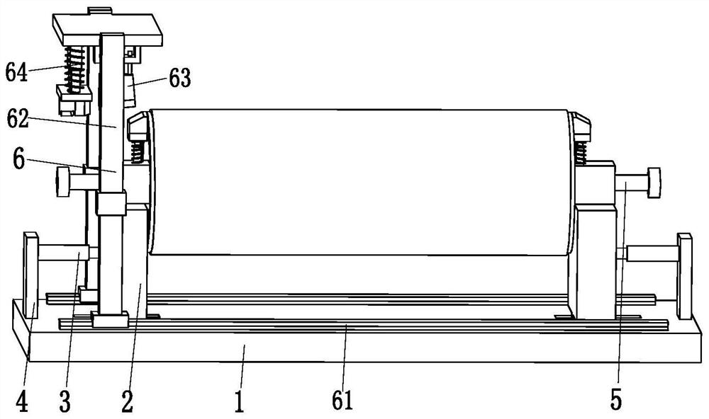
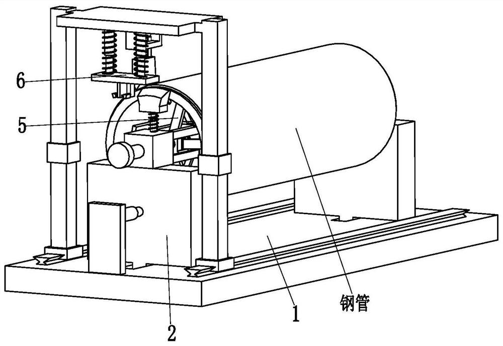
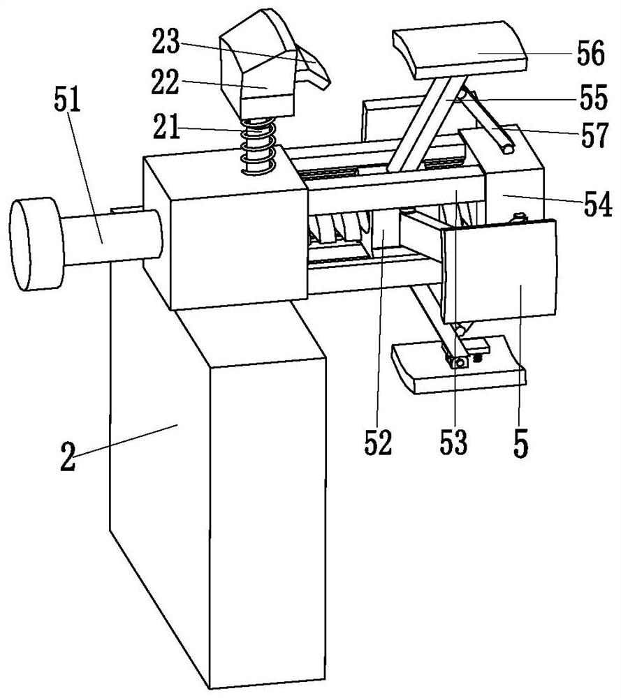
[0029] Such as Figure 1 to Figure 6 As shown, a steel structure building solid waste recycling and processing equipment includes a bottom plate 1, a locking slide plate 2, an adjusting cylinder 3, a cylinder support plate 4, a locking mechanism 5 and a cutting mechanism 6, and the top left and right ends of the bottom plate 1 are provided with There is a chute, and the locking slides 2 are symmetrically distributed on the left and right sides of the top of the bottom plate 1. The bottom of the locking slides 2 is connected to the chute by sliding fit. The inner ends are connected, and the outer end of the adjustment cylinder 3 is installed on the top of the base plate 1 through the cylinder support plate 4. A locking mechanism 5 is installed on the...


PUM


Abstract

The invention relates to a steel structure building solid waste recycling and processing equipment, which includes a base plate, a locking slide plate, an adjusting cylinder, a cylinder support plate, a locking mechanism and a cutting mechanism; a chute is arranged on the left and right ends of the top of the base plate, and the locking slide plate Symmetrically distributed on the left and right sides of the top of the bottom plate, the bottom of the locking slide is connected with the chute by sliding fit, the outer surface of each locking slide is connected with the inner end of an adjusting cylinder, and the outer end of the adjusting cylinder passes through the cylinder The support plate is installed on the top of the bottom plate, and a locking mechanism is installed on the inner surface of the upper end of each locking slide plate. The present invention can solve the problem existing in the separation of the protective layer of the steel pipe: the protective layer of the steel pipe cannot be completely separated due to uneven cutting force or certain deformation on the surface of the steel pipe when the protective layer of the steel pipe is cut; The incision position of the layer is turned outwards and so on.

Description

technical field [0001] The invention relates to the technical field of steel recycling, in particular to a recycling and processing equipment for steel structure building solid waste. Background technique [0002] The steel structure has the characteristics of light weight, high strength, good seismic performance, energy saving and environmental protection, and fast construction speed, and the steel used in the steel structure can be recycled; steel pipes are a kind of steel, and the amount of steel pipes used in steel structure buildings Increasing year by year, the section of steel pipe has the characteristics of smooth surface, no dead angle and small outer area, which not only helps to save anti-corrosion and fire-proof coatings, but also facilitates dust removal, prestressed steel wire ropes can be placed in the pipe, and internal prestress can be applied. [0003] When the steel pipe is in use, a protective layer of plastic material is generally set on its outer surfac...

Claims


Application Information

Patent Timeline
Patent Type & Authority Patents(China)
IPC IPC(8): B09B3/00B09B5/00B26D7/01B26D7/26B26D7/18B32B43/00
CPCB09B3/00B09B5/00B26D7/01B26D7/1818B26D7/2628B26D2007/013B32B43/00B32B43/003Y02W30/58Y02P70/10
Inventor 陈妹儿丁健
Owner 赣州市束薪再生资源有限公司
Learn More