
Rivet vibration feeding equipment for riveting machine core connecting rods and use method thereof

A technology of feeding equipment and rivets, which is applied in the field of rivet vibration feeding equipment for riveting connecting rods of machine cores. It can solve problems such as cross-rail jamming, riveting pressure deviation, troubles, etc., and achieve smooth movement and prevent jamming.

Active Publication Date: 2020-07-10
MAANSHAN NAITE INSTR TECH
View PDF7 Cites 0 Cited by
  • Summary
  • Abstract
  • Description
  • Claims
  • Application Information

AI Technical Summary

Problems solved by technology

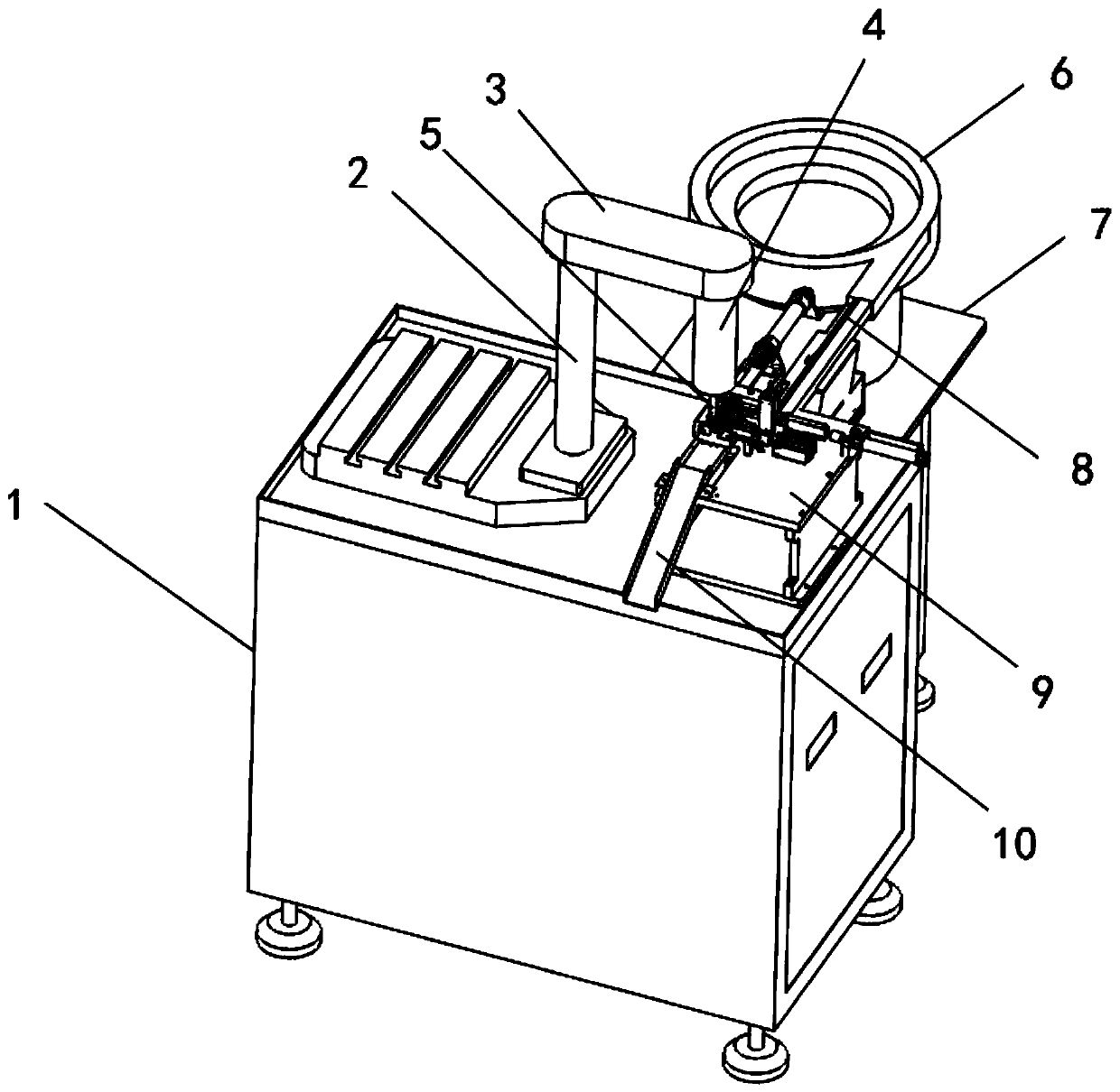
[0004] The object of the present invention is to provide a rivet vibration feeding device for riveting the connecting rod of the movement and its use method, which can solve the problem that when the existing equipment is in use, the rivet is conveyed into the horizontal due to the vibration feeding of the vibration plate After the rail passes, it is prone to non-orthogonal transmission, that is, tilting, which not only easily leads to deviations in subsequent riveting pressure, but also is extremely prone to the phenomenon of cross rail jamming. The phenomenon of jamming occurs, and at the same time, the existing equipment of this type still has the cross rail after the jamming, which is inconvenient to take out the rivets, and it is necessary to disassemble the cross rail to dig out the rivets, which is more troublesome

Method used


Image

  • Rivet vibration feeding equipment for riveting machine core connecting rods and use method thereof
  • Rivet vibration feeding equipment for riveting machine core connecting rods and use method thereof
  • Rivet vibration feeding equipment for riveting machine core connecting rods and use method thereof

Examples


Embodiment Construction

[0029] The technical solutions of the present invention will be clearly and completely described below in conjunction with the embodiments. Apparently, the described embodiments are only some of the embodiments of the present invention, not all of them. Based on the embodiments of the present invention, all other embodiments obtained by persons of ordinary skill in the art without creative efforts fall within the protection scope of the present invention.

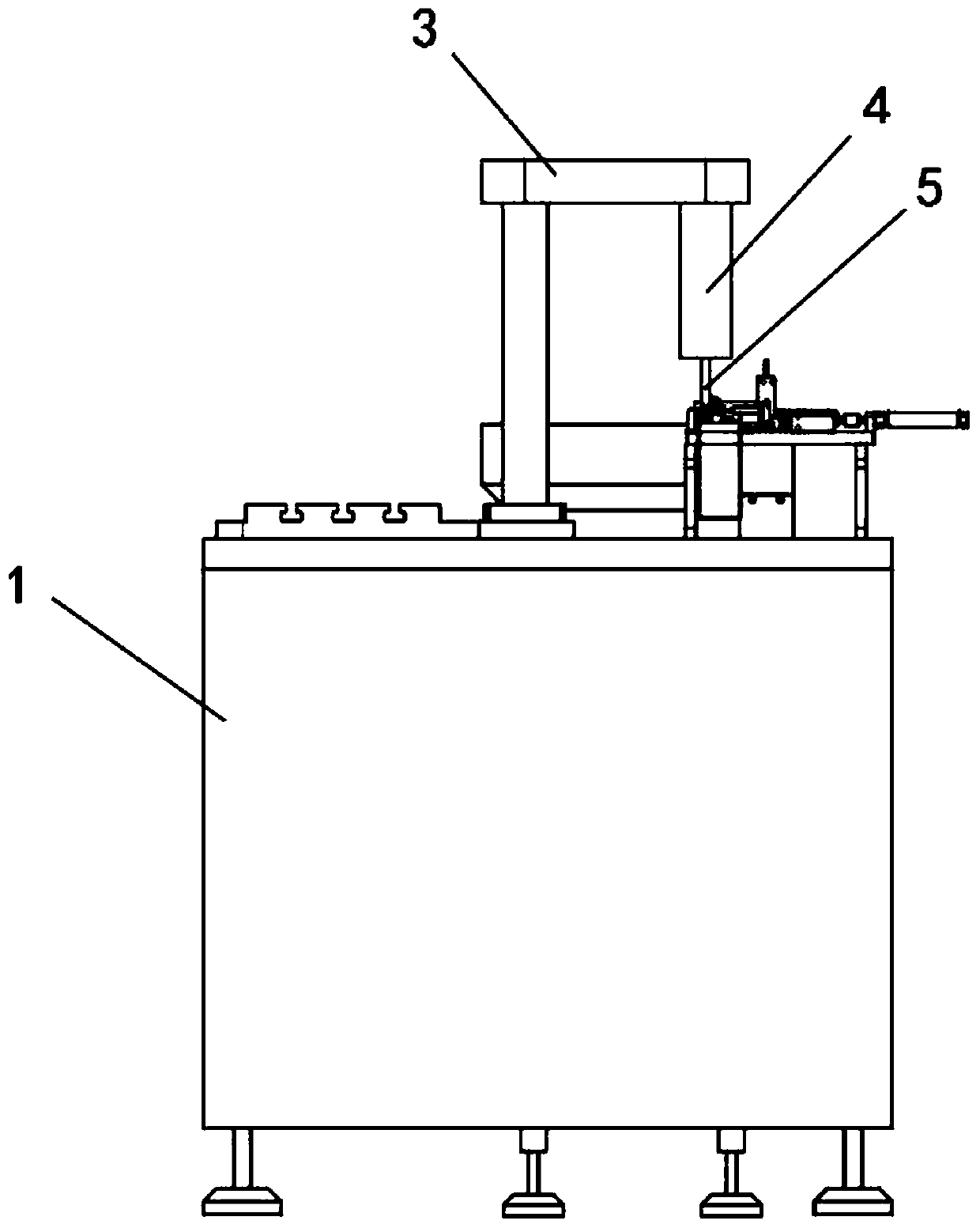
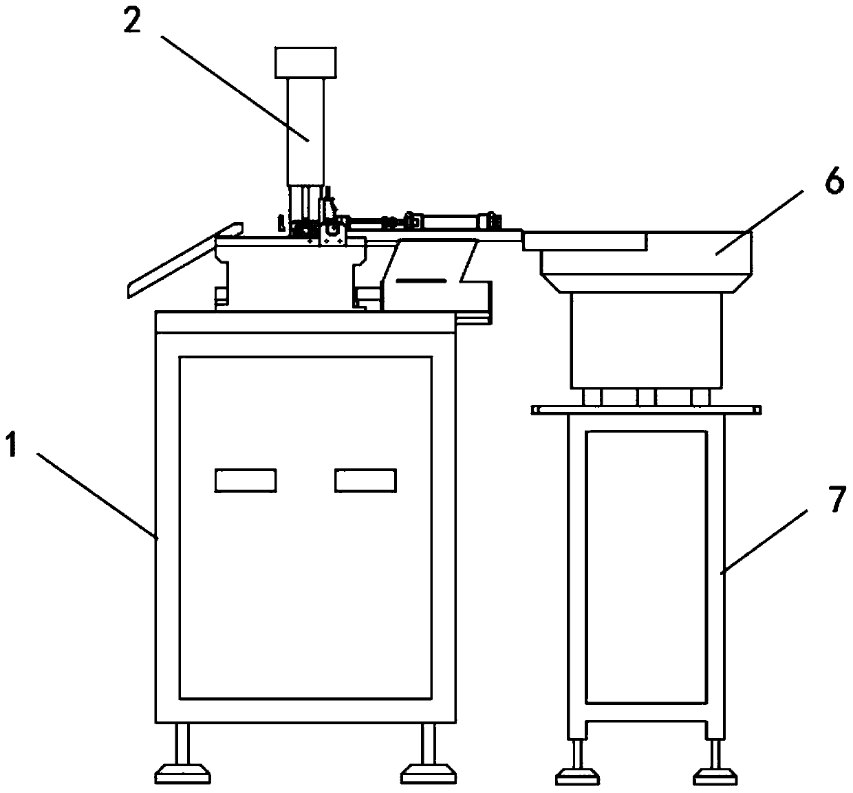
[0030] see Figure 1-8As shown, a rivet vibration feeding device for riveting connecting rods of a movement, including a base 1, a bracket 2, a side frame 7 and an operating table 9, a bracket 2 is fixed on the top of the base 1, and a riveting cylinder is fixed on the top of the bracket 2 3. A pneumatic rod 4 is connected to the bottom of the riveting cylinder 3, and a vertical punching head 5 is connected to the bottom of the pneumatic rod 4. One side of the bracket 2 is fixed with an operation table 9 on the top of the b...


PUM


Abstract

The invention discloses rivet vibration feeding equipment for riveting machine core connecting rods. The equipment comprises a base, a support, a side frame and an operating platform, the top of the base is fixedly provided with the support, the top end of the support is fixedly provided with a riveting air cylinder, the bottom of the riveting air cylinder is connected with a pneumatic rod, the bottom end of the pneumatic rod is connected with a vertical stamping head, and one side of the support is fixedly provided with the operating platform positioned at the top of the base. When existing equipment is used, due to the fact that a vibrating disc is used for vibration feeding, rivets are prone to non-normal transmission, namely inclination, after being conveyed into a transverse rail, thesubsequent riveting deviation is prone to being caused, the phenomenon that the transverse rail is clamped is extremely prone to occurring, the existing equipment cannot well avoid the phenomenon that clamping occurs due to oblique transmission of the rivets, meanwhile, the existing equipment also has the problems that the transverse rail after the clamping makes rivet taking inconvenient the transverse rail is required to be disassembled for taking out the rivets, and the process is troublesome.

Description

technical field [0001] The invention relates to the field of pressure gauge rivet feeding equipment, in particular to a rivet vibration feeding equipment for riveting connecting rods of a movement and a use method thereof. Background technique [0002] The movement connecting rod assembly is the core component inside the pressure gauge. The existence of the movement connecting rod assembly can convert the air pressure detected by the pressure gauge into the mechanical energy of reversing the pointer rotation. The movement connecting rod assembly is in the process of production, processing and assembly. In order to improve the riveting efficiency, there are vibrating feeding equipment on the market to automatically convey the rivets and complete the automatic riveting. However, there are still some defects in the existing equipment. , in the feeding process, due to the vibration feeding of the vibrating plate, the rivets are prone to non-orthogonal transmission after being tr...

Claims


Application Information

Patent Timeline
Patent Type & Authority Applications(China)
IPC IPC(8): B21J15/10B21J15/18B21J15/32B21J15/38
CPCB21J15/10B21J15/18B21J15/32B21J15/38
Inventor 束高祥高孝友陈亮
Owner MAANSHAN NAITE INSTR TECH
Learn More