
Screwdriver capable of automatically receiving and feeding screws

A screwdriver and screw technology, applied in screwdrivers, wrenches, wrenches, etc., can solve the problems of unguaranteed stability, low work efficiency, cumbersome operation, etc., and achieve good market application prospects, reasonable structure design, and simple operation methods. Effect

Pending Publication Date: 2020-07-10
SUZHOU VOCATIONAL UNIV
View PDF1 Cites 2 Cited by
  • Summary
  • Abstract
  • Description
  • Claims
  • Application Information

AI Technical Summary

Problems solved by technology

However, the prior art disclosed above has the following defects: 1. The electromagnet body is only used as a solution for the storage and release of the screws, and when the screws are stored, the electromagnet needs to be in a working state all the time so that the screws cannot be kept from falling, causing certain problems. 2. The electromagnet needs to be frequently switched on and off during use, and the direction of the screwdriver head needs to be reversed by manually adjusting the adjusting nut many times, which is cumbersome and time-consuming. Fixed, the stability cannot be guaranteed during use
Therefore, although the existing disclosed screwdriver that can automatically send screws has realized the function of sending screws, the operation is cumbersome and the work efficiency is low.

Method used


Image

  • Screwdriver capable of automatically receiving and feeding screws
  • Screwdriver capable of automatically receiving and feeding screws
  • Screwdriver capable of automatically receiving and feeding screws

Examples


Embodiment Construction

[0026] The present invention will be further described below in conjunction with specific embodiments, but the embodiments are only exemplary and do not constitute any limitation to the scope of the present invention. It should be understood by those skilled in the art that the details and forms of the technical solutions of the present invention can be modified or replaced without departing from the spirit and scope of the present invention, but these modifications and replacements all fall within the protection scope of the present invention.

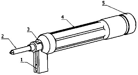
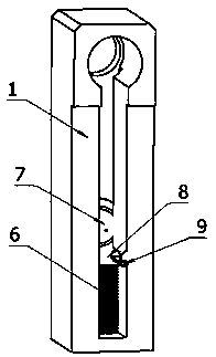
[0027] A screwdriver that automatically delivers screws, such as figure 1 As shown, the screwdriver includes a screwdriver magazine 1, a magnetic cutter head 2, a cutter head end cover 3, a handle 4 and a cutter head compression assembly, the magnetic cutter head 2 is arranged in the handle 4 and is made by the cutter head compression assembly. Telescopic movement in the handle 4, the cutter head end cover 3 and the handle 4 are conne...


PUM


Abstract

The invention provides a screwdriver capable of automatically receiving and feeding screws. The screwdriver includes a screwdriver screw storage box, a magnetic screwdriver head, a screwdriver head end cover, a hand shank and a screwdriver head compression assembly. The magnetic screwdriver head is arranged in the hand shank and telescopically moves in the hand shank through the screwdriver head compression assembly, and the screwdriver head end cover is in screwed connection with the hand shank at one end of the magnetic screwdriver head. The screwdriver screw storage box is internally provided with a screw storage groove, one end of the screwdriver screw storage box is provided with a screwdriver head penetrating through hole, the screwdriver head penetrating through hole penetrates through a rod body of the magnetic screwdriver head, and the screwdriver screw storage box is clamped at the bottom of the screwdriver head end cover to be fixed. The minimum diameter of a hole, far awayfrom the hand shank, of the screwdriver head penetrating through hole is larger than the external diameter of a screwdriver nut, and the minimum diameter of the hole in the other end is smaller than the external diameter of the screwdriver nut. The screwdriver can store and feed screws without power assistance, and energy saving and environment protection are achieved. The operation method is simple and convenient to perform, and the working efficiency is high. The screwdriver head is reasonable in structural design, stable in using and has good a market application prospect.

Description

technical field [0001] The invention relates to a screwdriver, in particular to a screwdriver for automatically sending and receiving screws. Background technique [0002] In production and life, we often need to use screwdrivers to disassemble and assemble various appliances. Usually, ordinary screwdrivers with various screw heads, electric screwdrivers, screwdrivers for automatic screw feeding in the assembly line, etc., can basically meet the needs. However, in the maintenance of small electronic products such as mobile phones, many times the manually stored screws are easy to lose, and during installation, tweezers are needed to assist in normal installation. This is time-consuming and labor-intensive, and causes great inconvenience to work and life. Therefore, a screwdriver that can automatically collect and send screws is required. [0003] The prior art solution discloses a screwdriver that can be accommodated and can automatically feed screws, application number 201...

Claims


Application Information

Patent Timeline
Patent Type & Authority Applications(China)
IPC IPC(8): B25B15/00B25B23/06B25B23/12
CPCB25B15/00B25B23/06B25B23/12
Inventor 刘旭刘昌金
Owner SUZHOU VOCATIONAL UNIV
Learn More