
A Tensioned Structure for Fully Actuated Finger Pneumatic Muscles in Robots

A pneumatic muscle and full-drive technology, applied in the field of robotics, can solve problems such as severe coupling of different joints, inability to dexterously operate the target object, and loose tendons and ropes.

Active Publication Date: 2021-05-18
ZHEJIANG UNIV OF TECH
View PDF7 Cites 0 Cited by
  • Summary
  • Abstract
  • Description
  • Claims
  • Application Information

AI Technical Summary

Problems solved by technology

It has the disadvantages that the different joints of the under-actuated hand are severely coupled and cannot perform dexterous manipulation of the target object
In addition, the actuators of most dexterous hands based on pneumatic muscles are placed at the end, and the middle is driven by a tendon rope, which can reduce the weight and volume of the end effector to a certain extent, but it also adds a disadvantage
Due to the fatigue damage of the tendon rope, long-term use will produce irreversible deformation, resulting in loosening of the tendon rope, thus forming a driving dead zone, which indirectly reduces the working space of the manipulator and increases the difficulty of precise control

Method used


Image

  • A Tensioned Structure for Fully Actuated Finger Pneumatic Muscles in Robots
  • A Tensioned Structure for Fully Actuated Finger Pneumatic Muscles in Robots
  • A Tensioned Structure for Fully Actuated Finger Pneumatic Muscles in Robots

Examples


Embodiment 1

[0027]A full-driven flexible handle with a highly driven passive adjustment based on pneumatic muscles, the main purpose is to increase the operation of the smart hand and improve the life of the smart hand.

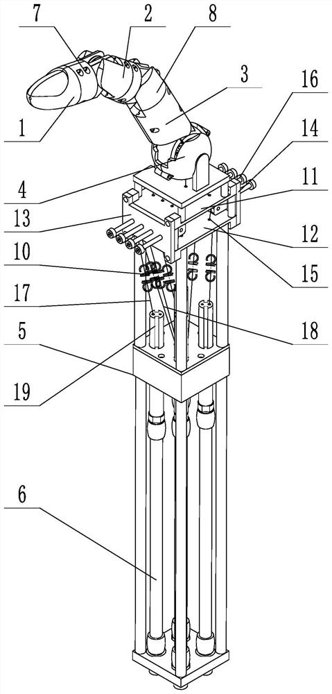
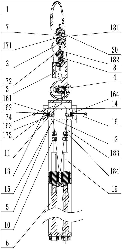
[0028]The informative hand of the present invention is mainly composed of a fully driven finger, a bottom bracket, and a necessary transmission as the five shape dimensions. Among them, iffigure 1 As shown, the full drive finger is an important part of the weak hand, which is mainly made from the distal finger end 1, the middle finger end 2, the near finger end 3, the ball joint 4, single-finger pneumatic muscle bracket 5, and pneumatic muscle 6 . The bottom bracket is supported by five pieces of support. Two-two support block hinges, and corresponding drives have corresponding drives on the corresponding hinge axis. The structural use of the bottom bracket is in that the support blocks can be rotated along the axis, facilitating increasing the degree of grant of finger operating...

Embodiment 2

[0040]Example 2 On the basis of the structures of Example 1, the following structure is included:

[0041]Such asFigure 5As shown, the two open places of the box structure are provided with corresponding third plate and fourth flat plate, and the third plate and the third plate are rotated and connected to the roller 22 of the cross section, the drum 22 in the axial direction. Outside the casing extends, the adjustment handle is disposed, and the drum is disposed above the pre-tightening bearing, the drum disguise the tendon rope. Adjusting the handle thread connection on the corresponding third tablet, by adjusting the adjustment handle, adjusting the roller 22 attitude, thereby adjusting its position with the tendon rope, and achieves all of the 8 zones. Combined with the pre-tightening screws to make tensioned convenience and custom tensioning of each tendon rope.


PUM


Abstract

The invention discloses a tensioning structure for the pneumatic muscles of the fully-driven fingers of a robot, aiming to solve the problem that the tendons of the under-actuated hand are easily deformed, resulting in a driving dead zone, reducing the working space of the manipulator and increasing its precise control. insufficient. The invention includes a driving tendon rope and a recovery tendon rope. The tendon rope is wound on a pulley in an "8" shape, and the tendon rope is fixedly connected to the pulley. The winding direction of the driving tendon rope and the recovery tendon rope is opposite. on tensioned tension springs. It can timely tension the tendon rope of the transmission, ensure the working space of the manipulator as long as possible, and reduce the difficulty of its precise control.

Description

Technical field[0001]The present invention relates to the field of robots, and more particularly, it relates to a tension structure for the robot full drive finger pneumatic muscle.Background technique[0002]At present, the pneumatic muscle drive is mainly used in the undressed driving method. Although the underfinctness can reduce the number of drivers, it reduces the complexity of the control, which makes it greatly reduced in weight, and volume, so the owed drive hand can There is a wide range of applications. However, in some scenarios that require fine operation, the different joints of the on-drive hand do be coupling, and the target object is unable to operate. In addition, most of the pneumatic muscles-based dexterous hands are placed at the end, and the intermediate tendon rope is driven to a certain extent, to a certain extent, the weight and volume of the end effector, but also add a drawback. Because there is fatigue damage, long-term use will generate unrecoverable defor...

Claims


Application Information

Patent Timeline
Patent Type & Authority Patents(China)
IPC IPC(8): B25J9/10B25J15/00
CPCB25J9/104B25J9/1075B25J15/0009
Inventor 朱李垚葛涵陈志培陶志成杨邦出鲍官军
Owner ZHEJIANG UNIV OF TECH
Learn More