
Spring energy storing brake device of emergency automated automobile

A technology of energy storage braking and automobile spring, applied in the direction of brake transmission, foot start device, brake, etc., can solve the problem of soft brake delay, improper increase of front air chamber volume, insufficient installation space of solenoid valve and surrounding Parts interfere with each other and other problems, so as to achieve the effect of no delay in braking and no increase in braking distance

Inactive Publication Date: 2018-11-23
王石麟
View PDF6 Cites 0 Cited by
  • Summary
  • Abstract
  • Description
  • Claims
  • Application Information

AI Technical Summary

Problems solved by technology

Usually, the driver will be extremely panicked after the brakes suddenly fail, and will instinctively and urgently continue to slam on the brakes to stop. If the car cannot stop, the driver will be even more panicked. It takes at least 2 seconds for the car control valve to be used by experienced drivers. Traffic accidents are inevitable. Moreover, after the brake fails, only one hand can be used to control the steering wheel, which is extremely unfavorable for the handling of dangerous situations.
For more than 30 years using the spring energy storage brake device, traffic accidents caused by brake failure have not been effectively curbed, and serious and serious traffic accidents caused by brake failure of urban buses with limited speeds have also occurred from time to time. It fully demonstrates that the existing manual spring energy storage brake device is used as an emergency brake to deal with the poor safety performance of the brake failure
When the fault exists, it is more difficult and unsafe for the driver to operate the parking control valve with one hand to keep the car running.
In order to solve the above-mentioned problems, there is a technology of adopting the method of balance tube to realize automatic emergency braking. Although it has the function of automatically implementing emergency brake in an instant without reaction and without using hands, the serious defect of its existence is that: due to the balance tube technology The emergency valve and the front air chamber of the spring energy storage type need to be connected with a long balance pipe, and the emergency valve and the front air chamber of the spring energy storage brake device are normally connected, which causes the cavity in the pipe to cause The volume of the front air chamber is increased improperly, which not only destroys the original car design, but also causes the delay of braking and the increase of braking distance, so it cannot be used.
Because the balance pipe technology requires multiple air pipes to be suspended from the car frame to the rear axle and then connected to each spring energy storage brake chamber, it not only increases the cost and difficulty, but also becomes a hidden danger of accidents due to the fragility of the suspended air pipes.
[0003] For this reason, Chinese Patent Publication No. CN103287418A disclosed on September 11, 2013 a method in which an automobile automatic emergency auxiliary braking device is directly connected with a solenoid valve and a spring energy storage brake air chamber intermediate. The automatic emergency braking device of a technical vehicle has defects such as the brake delay and softness due to the improper increase in the volume of the front air chamber caused by the balance tube. However, the solenoid valve is directly connected with the spring energy storage brake air chamber intermediate body in the implementation There is a serious defect that the installation space of the solenoid valve is not enough to interfere with the surrounding components and cannot be installed. To solve this problem, the structure of the intermediate body of the spring energy storage brake air chamber and the installation orientation on the rear axle must be changed, which will inevitably increase the cost. and difficulty, in the face of a large amount of engineering for various models, it is not conducive to the implementation and application

Method used


Image

  • Spring energy storing brake device of emergency automated automobile

Examples


Embodiment Construction

[0014] Below in conjunction with the accompanying drawings and preferred embodiments, the specific implementation, structure, features and effects of the spring energy storage braking device for emergency automatic vehicles proposed according to the present invention will be described in detail as follows.

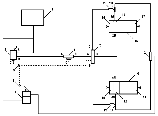
[0015] see figure 1 , the spring energy storage braking device for emergency automated automobiles of the present invention includes a brake valve 1, a quick release valve 2, a parking control valve 3, a relay valve 4, an emergency solenoid valve 5, a spring energy storage brake chamber A6, Air storage cylinder 7, foot control power switch 8, manual power switch 9, spring energy storage brake chamber B15, one-way valve A13, three-way A14, one-way valve B19, three-way B20, of which: spring energy storage brake The air chamber A6 is composed of the front air chamber A10, the rear air chamber A11, and the intermediate body A12. The spring energy storage brake air chamber B15 ...


PUM


Abstract

The invention discloses a spring energy storing brake device of an emergency automated automobile. The device comprises a brake valve (1), a quick release valve (2), a parking control valve (3), a relay valve (4), an emergency electromagnetic valve (5), a spring energy storing brake air chamber A (6), an air storing cylinder (7), a foot-control power switch (8), a hand-control power switch (9), aspring energy storing brake air chamber B (15), a one-way valve A (13), a three-way valve A (14), a one-way valve B (19) and a three-way valve B (20), and is characterized in that the spring energy storing brake air chamber A (6) is composed of a front air chamber (10), a back air chamber (11) and a middle body A (12), and the spring energy storing brake air chamber B (15) is composed of a front air chamber B (16), a back air chamber (17) and a middle body (18). The device is high in safety, reliable in performance and simple in structure, reduces the workload of installment and maintenance, and can be applicable to wide automobile types.

Description

technical field [0001] The invention belongs to the technical field of automobile braking, and in particular relates to an emergency automatic automobile spring energy storage braking device. Background technique [0002] The spring energy storage brake device is used as standard equipment on air brake vehicles (commonly known as air brakes). It has manual parking brake functions and emergency brake functions. Its parking brake functions and emergency brake functions are actually The same function responds to two different needs. It is called parking brake when parking, and it is called emergency brake when the brake fails. However, the driver must operate the same parking control valve with one hand when implementing the parking brake or emergency braking. The parking performance of this manual spring energy storage brake device is very reliable, but the safety efficiency as an emergency brake to deal with brake failure is very low, and the requirements for the driver's ...

Claims


Application Information

Patent Timeline
Patent Type & Authority Applications(China)
IPC IPC(8): B60T13/68B60T7/06B60T17/00
CPCB60T7/06B60T13/68B60T17/00
Inventor 王石麟
Owner 王石麟
Learn More