Automatic calibration method and calibration device for mechanical arm

An automatic calibration and robotic arm technology, applied in the directions of manipulators, program-controlled manipulators, manufacturing tools, etc., can solve the problems of affecting the positioning of marker objects, the error of the transformation coefficient of the two coordinate systems, and the difficulty of visual alignment, so as to reduce the correction time. , The effect of lowering the operating threshold and improving the calibration accuracy

Active Publication Date: 2021-09-07
DELTA ELECTRONICS JIANGSU
View PDF0 Cites 0 Cited by
  • Summary
  • Abstract
  • Description
  • Claims
  • Application Information

AI Technical Summary

Problems solved by technology

[0006] 2. When obtaining the coordinates of the manipulator, if the tool carried by the robot is large or irregular, it is difficult to achieve alignment by human vision, resulting in an error in the transformation coefficient of the two coordinate systems, which affects the positioning of the marker object during operation
[0007] 3. Because this method only solves the coordinate transformation coefficient before the operation in the whole operation, and the error caused by other bad operations in the subsequent operation can only be corrected by stopping

Method used


Image

  • Automatic calibration method and calibration device for mechanical arm
  • Automatic calibration method and calibration device for mechanical arm
  • Automatic calibration method and calibration device for mechanical arm

Examples


Embodiment Construction

[0075] Example embodiments will now be described more fully with reference to the accompanying drawings. Example embodiments may, however, be embodied in many forms and should not be construed as limited to the embodiments set forth herein. Rather, these embodiments are provided so that this disclosure will be thorough and complete, and will fully convey the concept of the example embodiments to those skilled in the art. The same reference numerals denote the same or similar structures in the drawings, and thus their repeated descriptions will be omitted.

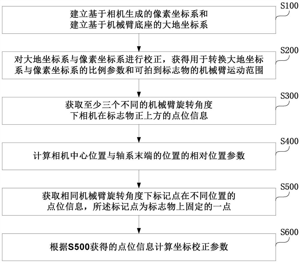
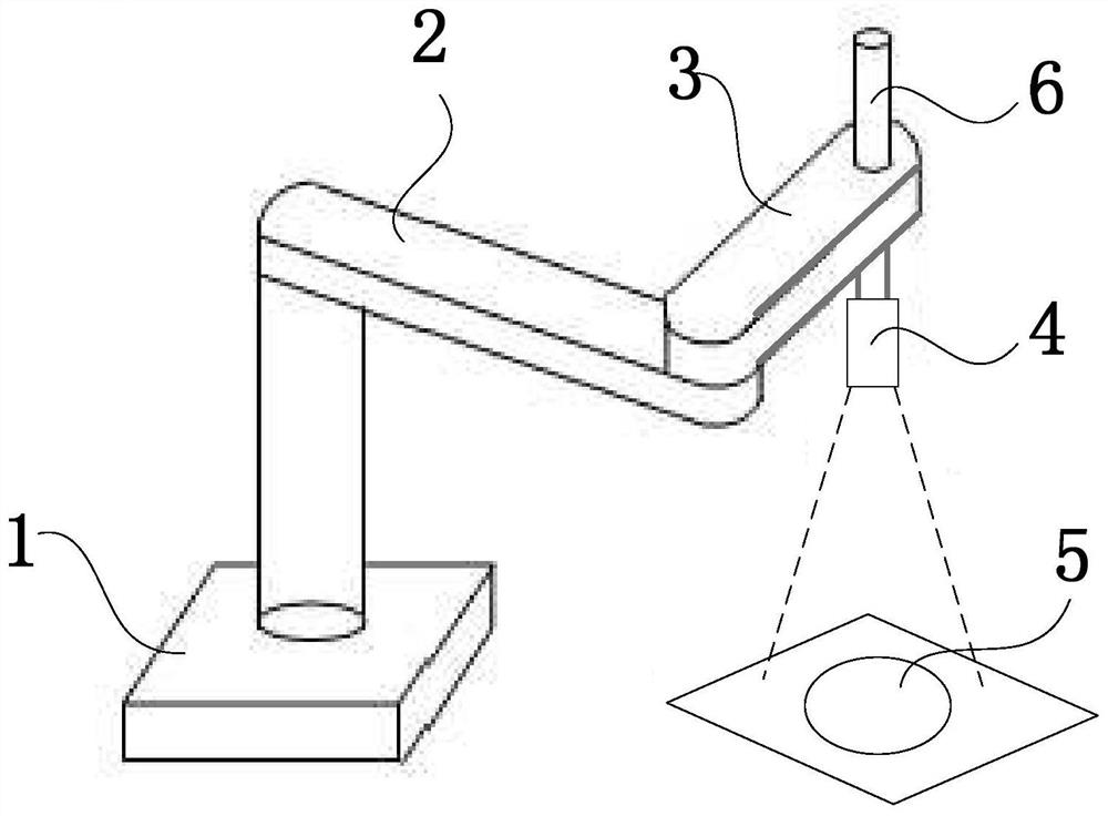
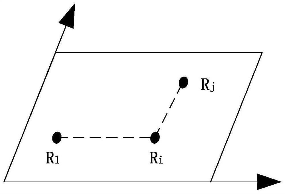
[0076] figure 1 It is a schematic flow chart of the automatic calibration method of the manipulator of the present invention. figure 2 It is a schematic diagram of the automatic calibration device of the manipulator of the present invention. image 3 is the image in the field of view of the camera in the present invention. Such as Figures 1 to 3 As shown, the present invention provides a method for automatic calibrat...


PUM


Abstract

The invention provides a mechanical arm automatic calibration method and a calibration device. The calibration method includes the following steps: establishing a pixel coordinate system based on the camera and establishing a geodetic coordinate system based on the base of the manipulator; correcting the geodetic coordinate system and the pixel coordinate system to obtain It is used to convert the scale parameters between the earth coordinate system and the pixel coordinate system and the movement range of the manipulator that can capture the marker; obtain the point information of the camera directly above the marker under at least three different rotation angles of the manipulator; calculate the camera center The relative position parameter of the position and the position of the end of the shaft system; obtain the point information of the marked point at different positions under the same rotation angle of the manipulator, and the marked point is a fixed point on the marker; calculate the coordinate correction parameters according to the point information. The invention simplifies the calibration process, greatly reduces the correction time of the earth coordinate system and the pixel coordinate system, improves the calibration accuracy, and lowers the operation threshold.

Description

technical field [0001] The invention relates to the field of calibration of a tool coordinate system, in particular to a method for automatic calibration of a mechanical arm and a calibration device. Background technique [0002] Industrial robot is a typical representative of mechatronics. It has been widely used in all walks of life in industry to continuously improve production efficiency. With the continuous development of robotics, computer technology and image processing technology, the application of industrial robots with vision systems is becoming more and more extensive. As the main way for industrial robots to obtain environmental information, the vision system can improve the identification and positioning capabilities of industrial robots and enhance the flexibility of industrial robots. In the application of industrial robots and vision systems, it is necessary to obtain the pixel coordinates of the marker T in the image through the vision system, and calculat...

Claims


Application Information

Patent Timeline
Patent Type & Authority Patents(China)
IPC IPC(8): B25J9/16
CPCB25J9/1653
Inventor 颜良益杨杰伍蒙王志芳
Owner DELTA ELECTRONICS JIANGSU
Why Eureka
Try Eureka