Supercharge Your Innovation With Domain-Expert AI Agents!

Manipulator for underwater operation

A technology of underwater operation and manipulator, applied in the field of manipulator, can solve the problems of high density of salt water, high water pressure, small contact area, etc.

Active Publication Date: 2020-07-10
泉州市泉腾机械科技有限公司
View PDF12 Cites 1 Cited by
  • Summary
  • Abstract
  • Description
  • Claims
  • Application Information

AI Technical Summary

Problems solved by technology

[0003] Since the underwater salvage manipulator clamps the submerged object through the gripper at the end, when the underwater salvage manipulator salvages the spherical object in salt water, the contact area between the spherical object and the gripper is small, and the The density of water is so high that the water pressure will also be too high, so that when the underwater salvage manipulator salvages spherical objects in this environment, it is easy for the spherical object to fall off before it comes out of the water.

Method used


Image

  • Manipulator for underwater operation
  • Manipulator for underwater operation
  • Manipulator for underwater operation

Examples


Embodiment 1

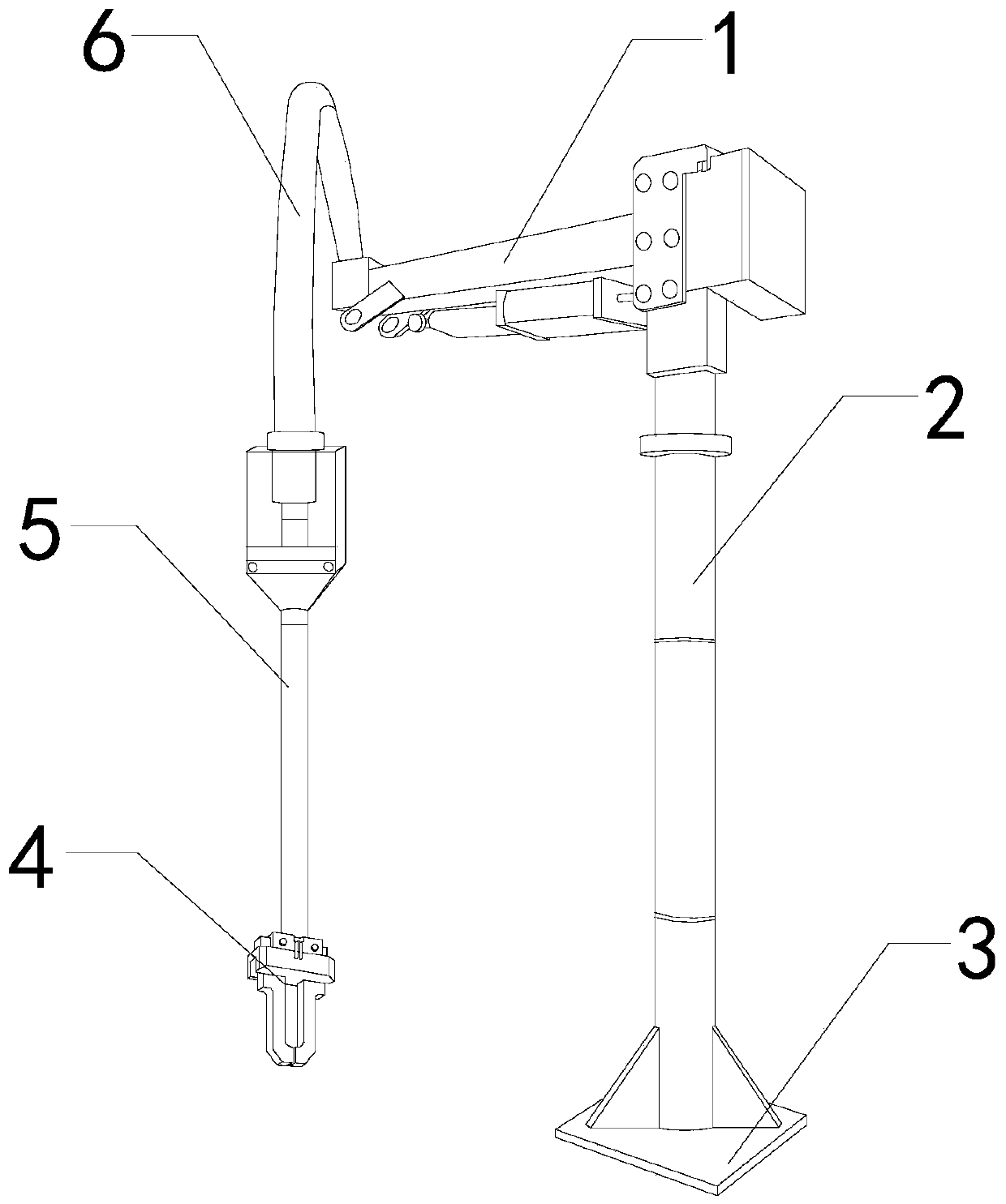
[0028] For example figure 1 -example Figure 5 Shown:

[0029] The invention provides a manipulator for underwater operation, its structure includes a steering rod 1, a support rod 2, a base 3, a gripper 4, a telescopic rod 5, and a connecting rod 6, and the steering rod 1 is movably engaged with the support rod 2 The upper end position of the support rod 2 is welded with the base 3, one end of the connecting rod 6 is connected with the telescopic rod 5, and the other end of the connecting rod 6 is embedded in the left end position of the steering rod 1, and the clamping The device 4 is installed at the bottom position of the telescopic rod 5.

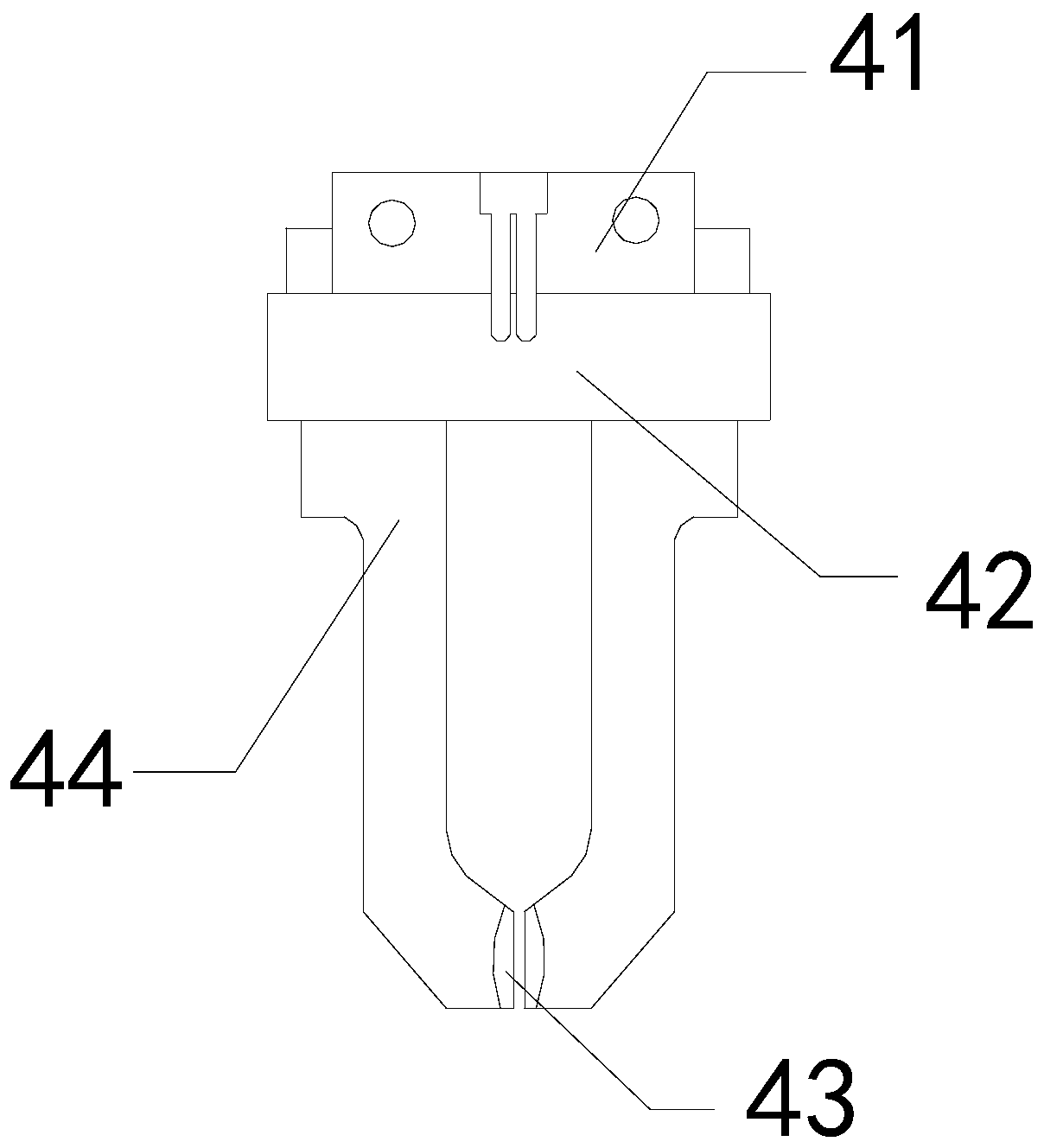
[0030] Wherein, the clamper 4 includes a connection base 41, a guide rail 42, a fixing mechanism 43, and a clamping block 44, the connection base 41 is embedded in the upper end of the guide rail 42, and the fixing mechanism 43 and the clamping block 44 are Integrated structure, the clamping block 44 is movably engaged with the lowe...

Embodiment 2

[0037] For example Image 6 -example Figure 9 Shown:

[0038] Wherein, the bottom block a23 includes a drainage mechanism b1 and a disc body b2, the drainage mechanism b1 and the disc body b2 are an integrated structure, and the drainage mechanism b1 has a circular structure, which can The moisture inside the disc body b2 is discharged.

[0039] Wherein, the drainage mechanism b1 includes an opening and closing piece b11, a frame body b12, a receiving block b13, and a direction limiting mechanism b14. The opening and closing piece b11 is movably engaged with the receiving block b13, and the receiving block b13 and the frame body b12 are Integrated structure, the direction limiting mechanism b14 is embedded and connected with the opening and closing piece b11, and the moisture inside the object generates an upward thrust on the opening and closing piece b11, so that the opening and closing piece b11 can be opened, so that the moisture inside the mechanism can be discharged ...


PUM


Abstract

The invention discloses a manipulator for underwater operation. The manipulator structurally comprises a steering rod, a support rod, a base, a holder, a telescopic rod and a joint rod. The steering rod is movably clamped to the upper end position of the support rod. The support rod is welded to the base. One end of the joint rod is connected with the telescopic rod, and the other end of the jointrod is fixedly embedded in the left end position of the steering rod. The holder is mounted at the bottom position of the telescopic rod. A fixing mechanism on the clamping device can fix a sphericalobject. When the clamping block clamps the spherical object, an adsorption mechanism can be contracted inwards by the extrusion force, generated when the spherical object is clamped, on the adsorption mechanism on the fixing mechanism, water in a disc body can be drained through a drainage mechanism on the disc body, and the internal water can be drained through an opening and closing piece on the drainage mechanism when the disc body is extruded by the spherical object and deformed.

Description

technical field [0001] The invention relates to the field of manipulators, in particular to a manipulator for underwater operation. Background technique [0002] The underwater salvage manipulator is mainly used to salvage the sunken objects. It can reach the bottom of the water through the telescopic arm, and then clamp the sunken objects through the gripper at the end, so that the sunken objects can be brought out. The water surface is a common equipment in the salvage industry. Based on the above description, the inventors found that an existing underwater manipulator mainly has the following deficiencies, for example: [0003] Since the underwater salvage manipulator clamps the submerged object through the gripper at the end, when the underwater salvage manipulator salvages the spherical object in salt water, the contact area between the spherical object and the gripper is small, and the The density of water is so high that the water pressure will also be too high. As a...

Claims


Application Information

Patent Timeline
IPC IPC(8): B25J15/06B25J15/08B25J11/00
CPCB25J15/0683B25J15/08B25J11/00
Inventor 黄晓明
Owner 泉州市泉腾机械科技有限公司
Features
  • R&D
  • Intellectual Property
  • Life Sciences
  • Materials
  • Tech Scout
  • Unparalleled Data Quality
  • Higher Quality Content
  • 60% Fewer Hallucinations
Learn More