Calender

The technology of a calender and a frame is applied in the field of shoe machinery, which can solve the problems of poor heating effect of the heating plate, easy deformation and damage of the heating plate, poor adhesion effect of the shoe upper, etc., so as to improve the heating effect and facilitate installation and maintenance. , The effect of shoe upper pressing effect is good

Pending Publication Date: 2020-07-10
泉州市颖邦机械设备有限公司
View PDF0 Cites 0 Cited by
  • Summary
  • Abstract
  • Description
  • Claims
  • Application Information

AI Technical Summary

Problems solved by technology

[0004] 1. The upper pressure roller and the upper and lower cloth guide rollers of the calender are fixed, and the tightness or looseness of the entire high-temperature endless belt can be adjusted by moving the lower pressure roller, but because the shoe upper is always fixed at the entrance and middle part of the high-temperature endless belt space, so the upper is not really squeezed during the whole bonding process, so the upper bonding effect is poor
[0005] 2. The heating effect of the heating plate is poor, so that the bonding effect of the upper is not good
Moreover, the heating plate is easily deformed and damaged by heat, which affects work efficiency and increases maintenance costs

Method used


Image

  • Calender
  • Calender
  • Calender

Examples


Embodiment 1

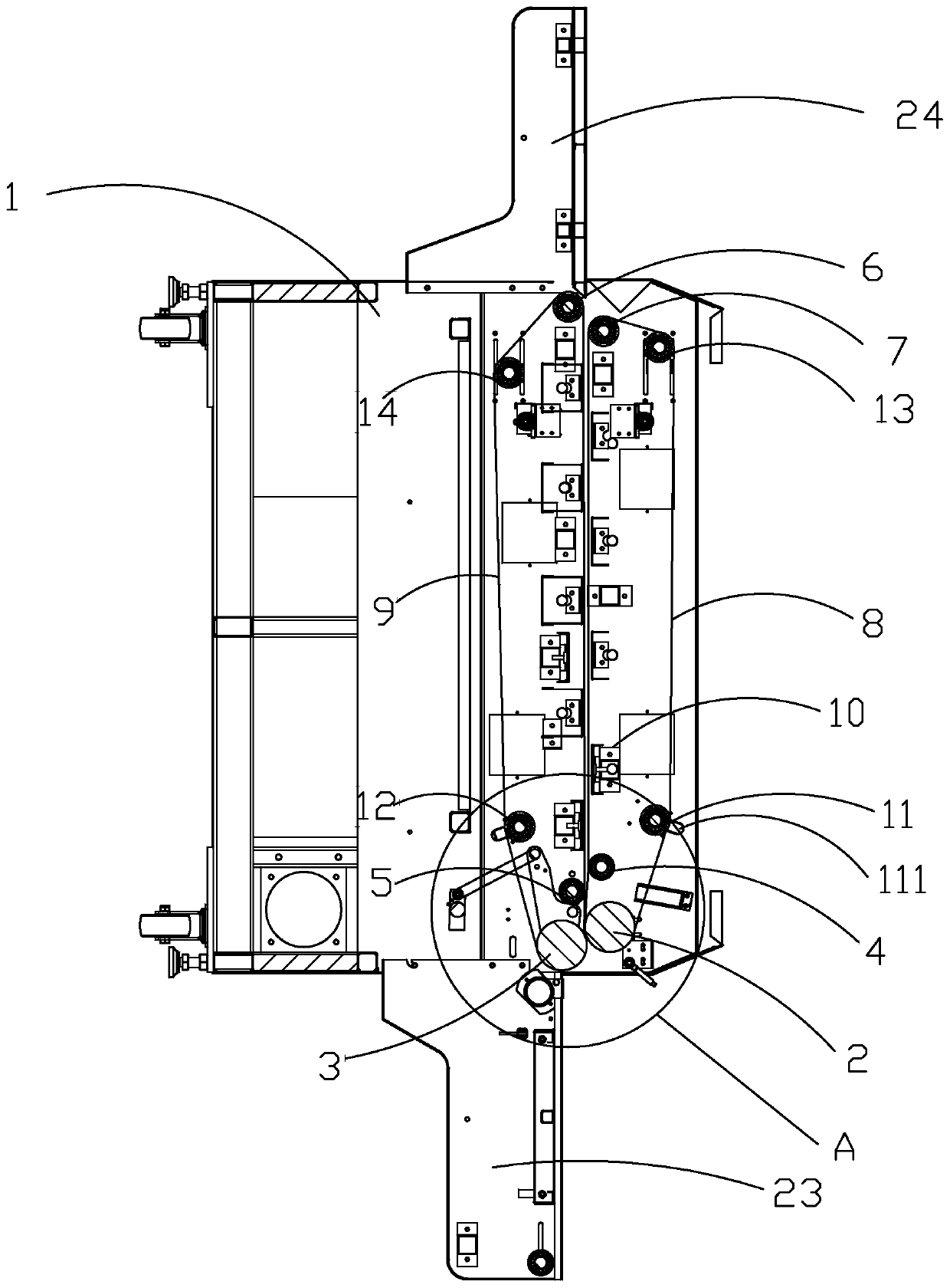
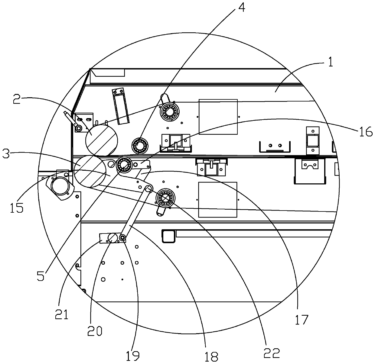
[0039] refer to Figure 1-Figure 8The embodiment of the present invention discloses a calender, which includes a frame 1, on which an upper pressing roller 2, an upper fabric guide roller 4 and an upper support roller 7 are rotatably arranged through bearings. The pressure roller 2, the upper cloth guide roller 4 and the upper supporting roller 7 are wound with an upper high-temperature endless belt 8, and the frame 1 is located below the upper high-temperature annular belt 8 and is rotatably provided with a lower pressure roller 3 and a lower guide roller 3 through bearings. The cloth roller 5 and the lower idler 6, the lower pressure roller 3, the lower cloth guide roller 5 and the lower idler 6 are wound with a lower high-temperature endless belt 9, and the output shaft 21 of the upper pressure roller 2 is fixed with a The first sprocket 114, the output shaft 31 of the lower pressure roller 3 is fixed with the second sprocket 113, the frame 1 is provided with a first drive ...

Embodiment 2

[0047] according to Figure 9 , based on the above solution, the second adjustment device in the present invention can also be: the second adjustment device includes an adjustment screw 3', an adjustment slot 2' is opened on the frame 1', and an adjustment groove 2' is opened on the frame 1'. There is also a mounting hole 4' that is connected to the adjustment groove 2' to facilitate the installation of the tension roller. One end of the adjustment screw 3' is fixed with a first fixed block 7', and the first fixed block 7' is respectively connected by screws 8'. Locked on the upper first tension roller 11' and the lower first tension roller (not shown in the figure), the frame 1' is fixed with a second fixed block 5', and the adjustment screw 3' The other end passes through the second fixing block 5' and passes through the second fixing block 5', the adjusting screw 3' is sleeved with a nut 6', and the nut 6' is connected to the second fixing block 5'. Block 5' resists. When...


PUM


Abstract

The invention provides a calender which is simple in structure, good in heating effect, convenient to adjust and good in vamp press-fitting effect. The calender comprises a rack, an upper loop and a lower loop are arranged on the rack, the lower loop is located below the upper loop, and a heating device for heating vamp materials is arranged on the rack and located between the upper loop and the lower loop. A pressure adjusting device for adjusting press-fitting of the vamp materials is arranged on the rack. A first driving device for driving the upper loop and the lower loop to move is arranged on the rack, and the heating device comprises a heating plate, a U-shaped heat guiding plate and a heat insulation plate, wherein the heat insulation plate is located below the U-shaped heat guiding plate, the heating plate is arranged between the heat insulation plate and the U-shaped heat guiding plate, the heating plate abuts against the U-shaped heat guiding plate and abuts against the heatinsulation plate, the U-shaped heat guiding plate and the heat insulation plate are fixedly connected, and the heat insulation plate is fixedly connected with the rack.

Description

technical field [0001] The invention relates to the technical field of shoe machinery, in particular to a calender. Background technique [0002] At present, in the shoe industry, flying woven uppers can be said to be a popular trend in the shoe industry. Whether it is Adidas, Nike, Anta or 361°, the main shoes in recent years are uppers. Now many footwear brands are launching fly-woven upper shoes one after another. This kind of flat-knitted fly-knit upper came from abroad at first. At that time, it was popular abroad for a while. At the beginning, people were surprised when they saw the real thing. They were surprised that the product was so good and how such a product was produced. , and the next 3D flying woven upper is bound to become a popular trend in the future, especially some high-end jogging shoes and casual shoes will be very suitable for this upper. Domestic manufacturers have also begun to use 3D upper thermal fuses, and are constantly researching and develop...

Claims


Application Information

Patent Timeline
Patent Type & Authority Applications(China)
IPC IPC(8): B29C59/04B29C35/02B29L31/50
CPCB29C35/02B29C59/002B29C59/04B29L2031/505
Inventor 陈聪颖
Owner 泉州市颖邦机械设备有限公司
Why Eureka
Try Eureka