Rapid drying device for printed matter

A technology for rapid drying and printing, applied in printing, printing machines, general parts of printing machinery, etc., can solve the problem of uneven heating of printed materials, achieve uniform heating and improve drying efficiency.

Inactive Publication Date: 2020-07-10
李明辉
View PDF0 Cites 6 Cited by
  • Summary
  • Abstract
  • Description
  • Claims
  • Application Information

AI Technical Summary

Problems solved by technology

[0003] During the drying process of the existing printed mat

Method used


Image

  • Rapid drying device for printed matter
  • Rapid drying device for printed matter
  • Rapid drying device for printed matter

Examples


Embodiment 1

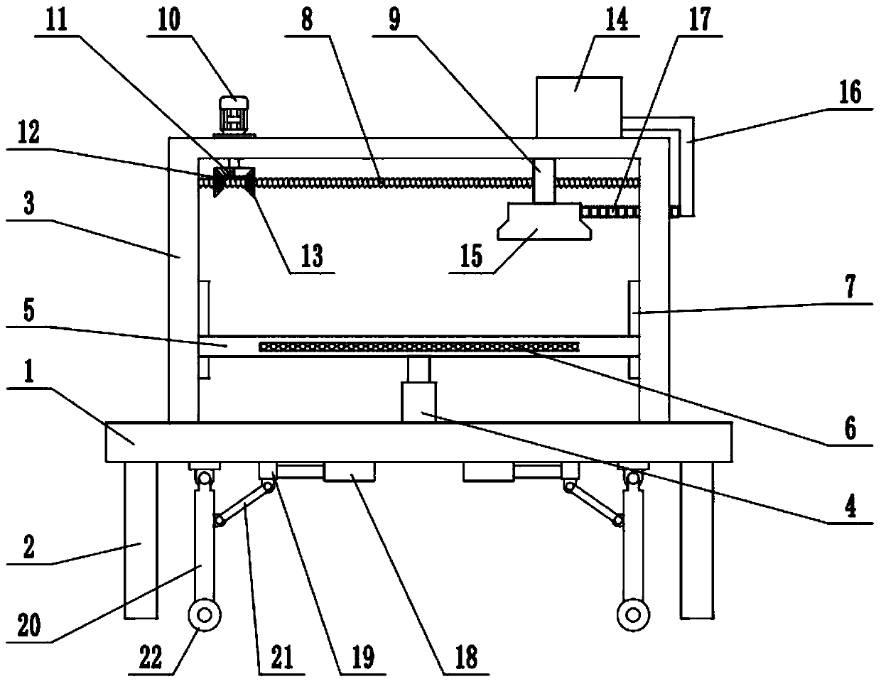
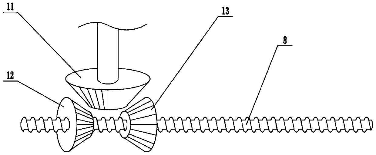
[0020] see Figure 1-3 , in an embodiment of the present invention, a printed matter rapid drying device includes a workbench 1, a drying plate 5, a hot air blower 14 and an air outlet 15, the lower surface of the workbench 1 is equipped with a foot 2, and the upper surface of the workbench 1 An oven body 3 is fixedly connected, and an oven door is installed on the side wall of the oven body 3. A telescopic mechanism 4 is fixedly connected to the upper surface of the workbench 1. The telescopic mechanism 4 is an electro-hydraulic telescopic cylinder. The top end of the telescopic mechanism 4 is fixedly connected with a The drying plate 5 is provided with a screw rod 8 above the drying plate 5, and the left and right ends of the screw rod 8 are respectively connected to the side wall of the oven body 3 in rotation. The screw rod 8 is covered with a slider 9, and the slider 9 It is threadedly connected with the screw mandrel 8, and the upper surface of the slider 9 is slidingly ...

Embodiment 2

[0022] On the basis of Embodiment 1, guide rails 7 are installed on the side walls of the oven box body 3, and the edges of the drying plate 5 are slidably connected with the guide rails 7 to control the expansion and contraction of the telescopic mechanism 4, which can drive the drying plate 5 to move up and down, and adjust the drying temperature. The height of the drying plate 5, the inside of the drying plate 5 is equipped with an electric heating plate 6, and the printed matter to be dried is placed on the drying plate 5, and the electric heating plate 6 can be used to heat the printed matter to improve the drying efficiency.

Embodiment 3

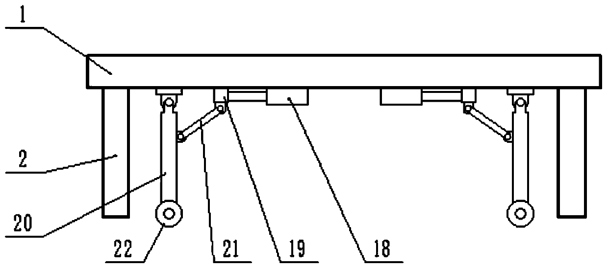
[0024] On the basis of Embodiment 1, a moving mechanism is installed on the bottom of the workbench 1, and the moving mechanism includes a cylinder 18, a moving block 19, a movable rod 20, a connecting rod 21 and a roller 22, and the lower surface of the workbench 1 is fixedly connected with a cylinder 18 , the protruding end of the cylinder 18 is fixedly connected with a moving block 19, the upper surface of the moving block 19 is slidingly connected with the lower surface of the workbench 1, the moving block 19 can slide left and right, and the lower surface of the workbench 1 is hinged with a movable rod 20, which is movable The lower end of bar 20 is equipped with roller 22, and the lower surface of moving block 19 is hinged with connecting rod 21, and the lower end of connecting rod 21 is hinged with the middle part of movable rod 20, and the extension of control cylinder 18 can drive moving block 19 to move laterally, thereby through The connecting rod 21 drives the movab...


PUM


Abstract

The invention relates to the field of drying equipment, in particular to a rapid drying device for printed matter. The rapid drying device comprises a workbench, a drying plate, an air heater and an air outlet, wherein supporting legs are arranged on the lower surface of the workbench, a drying oven body is fixedly connected to the upper surface of the workbench, and a telescopic mechanism is fixedly connected to the upper surface of the workbench; the drying plate is fixedly connected to the top end of the telescopic mechanism, a lead screw is arranged above the drying plate, and the left endand the right end of the lead screw are rotationally connected with the side wall of the drying oven body; and the lead screw is provided with a sliding block in a sleeved mode, and the air outlet isfixedly connected to the lower surface of the sliding block. The lower surface of the printed matter is heated through an electric heating plate, the printed matter on the drying plate is dried through the air heater, and in the drying process, the air outlet moves left and right, so that the printed matter is heated more evenly; and the device can dry the upper surface and the lower surface of the printed matter at the same time, and solves the problem that the printed matter is not heated evenly enough in the drying process through existing printed matter drying equipment.

Description

technical field [0001] The invention relates to the field of drying equipment, in particular to a quick drying device for printed matter. Background technique [0002] Printed matter is a variety of printed products and a general term for various finished products produced using printing technology. In daily life, people come into contact with newspapers, books and magazines, maps, posters, advertisements, envelopes, letterheads, portfolios, trademarks, labels, business cards, invitations, banknotes, greeting cards, desk calendars, wall calendars, picture albums, various cards, Packaging boxes, gift boxes, circuit boards, etc., are all in the category of printed matter. Printed matter is almost full of people's clothing, food, housing, and transportation, and it is very closely related to people's lives. [0003] During the drying process of the existing printed matter drying equipment, the printed matter is not heated evenly. Contents of the invention [0004] The obje...

Claims


Application Information

Patent Timeline
IPC IPC(8): B41F23/04
CPCB41F23/0436B41F23/0459B41F23/0466
Inventor 李明辉
Owner 李明辉
Why Eureka
Try Eureka