Exhaust type valve bag powder filling machine
A technology of exhaust valve and filling machine, which is applied in the directions of packaging, transportation and packaging, and the type of packaging items, can solve the problems of high labor cost, troublesome operation, easy powder falling, etc., and achieves low labor cost and convenient operation. Effect
- Summary
- Abstract
- Description
- Claims
- Application Information
AI Technical Summary
Problems solved by technology
Method used
Image

Examples
Embodiment 1
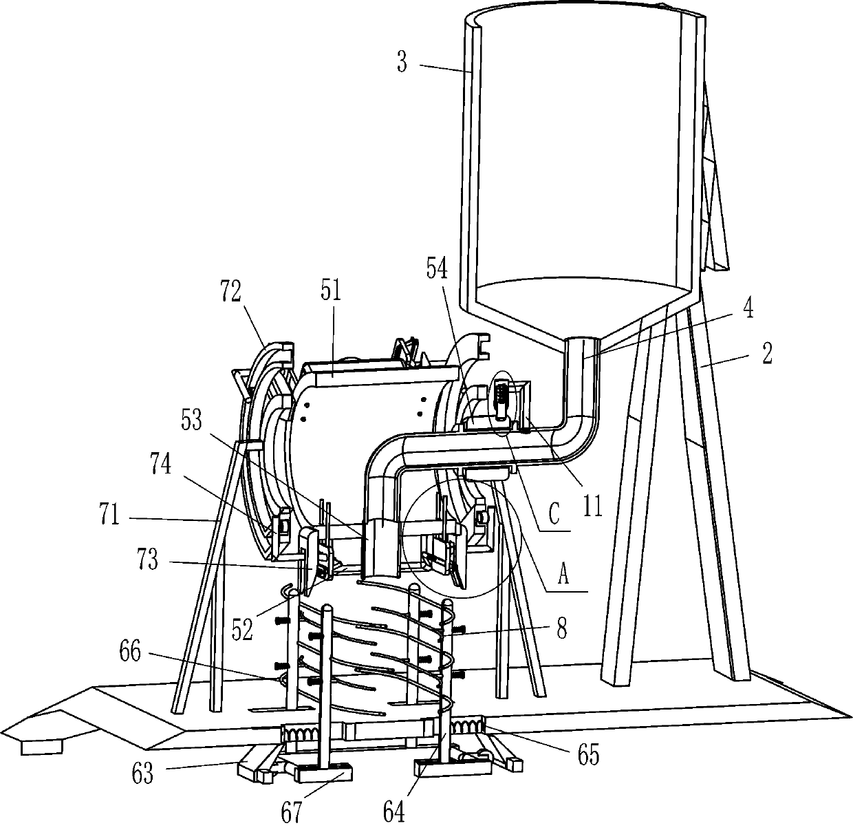
[0022] refer to Figure 1-Figure 3 , an exhaust type valve pocket powder filling machine, including a base 1, a support frame 2, a placement cylinder 3, a special-shaped tube 4, a guide mechanism 5 and a limit mechanism 6, and the right side of the top of the base 1 is fixed with a support frame 2 , the top of the support frame 2 is fixedly connected with a placement tube 3, and the middle of the bottom of the placement tube 3 is connected with a special-shaped tube 4. The special-shaped tube 4 communicates with the inside of the placement tube 3, and the left part of the special-shaped tube 4 is provided with a guide mechanism 5 that can discharge the powder. The guiding mechanism 5 is in contact with the special-shaped pipe 4, and the left part of the base 1 is provided with a limiting mechanism 6 capable of limiting the position of the valve pocket.
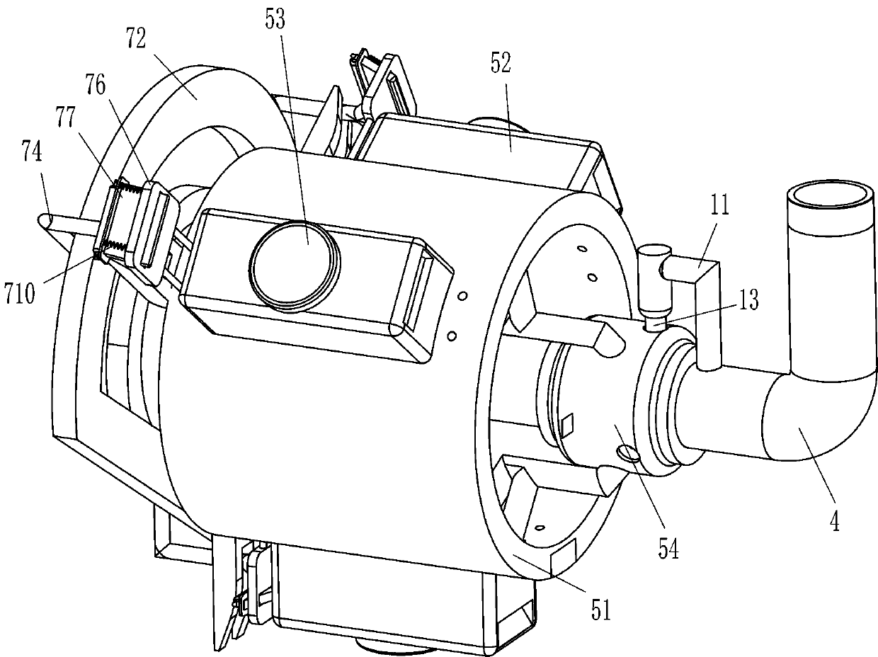
[0023] The guide mechanism 5 includes a circular cylinder 51, a fixed block 52, a discharge pipe 53 and a rotary block 54. T...
Embodiment 2
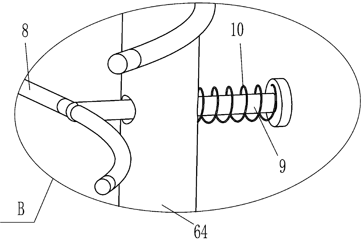
[0029] refer to Figure 1-Figure 4 Compared with Embodiment 1, the main difference of this embodiment is that in this embodiment, a clamping mechanism 7 is also included, and the clamping mechanism 7 includes a support rod 71, a special-shaped groove frame 72, a u-shaped block 73, and an L-shaped rod 74 , guide rod 75, vertical plate 76, movable plate 77, roller 79 and second spring 710, base 1 top left and right sides all are fixedly connected with two support rods 71, left and right sides support rods 71 are positioned at movable rod 64 left and right sides Side, between the tops of the two support rods 71 on the left side and between the tops of the two support rods 71 on the right side are fixedly connected with a special-shaped groove frame 72, and the sliding type in the special-shaped groove frame 72 is provided with three corresponding to the fixed block 52 Roller 79, the outer end of roller 79 is affixed with L-shaped bar 74, and the inner end of L-shaped bar 74...
PUM
 Abstract
Description
Claims
Application Information
 - R&D Engineer
- R&D Manager
- IP Professional
- Industry Leading Data Capabilities
- Powerful AI technology
- Patent DNA Extraction
Browse by: Latest US Patents, China's latest patents, Technical Efficacy Thesaurus, Application Domain, Technology Topic.
© 2024 PatSnap. All rights reserved.Legal|Privacy policy|Modern Slavery Act Transparency Statement|Sitemap