

Fluid pressure type rotation driving device
A technology of rotary drive device and liquid pressure, which is applied in the direction of reaction engine, hydroelectric power generation, engine components, etc., can solve the problems of high manufacturing cost, complex engine structure, low rotation strength of electric motor, etc., and achieves strong driving force and simple structure. , the effect of strong controllability
- Summary
- Abstract
- Description
- Claims
- Application Information
AI Technical Summary
Problems solved by technology
Method used
Image

Examples
Embodiment Construction
[0020] The following will clearly and completely describe the technical solutions in the embodiments of the present invention with reference to the accompanying drawings in the embodiments of the present invention. Obviously, the described embodiments are only some of the embodiments of the present invention, not all of them. Based on the embodiments of the present invention, all other embodiments obtained by persons of ordinary skill in the art without making creative efforts belong to the protection scope of the present invention.
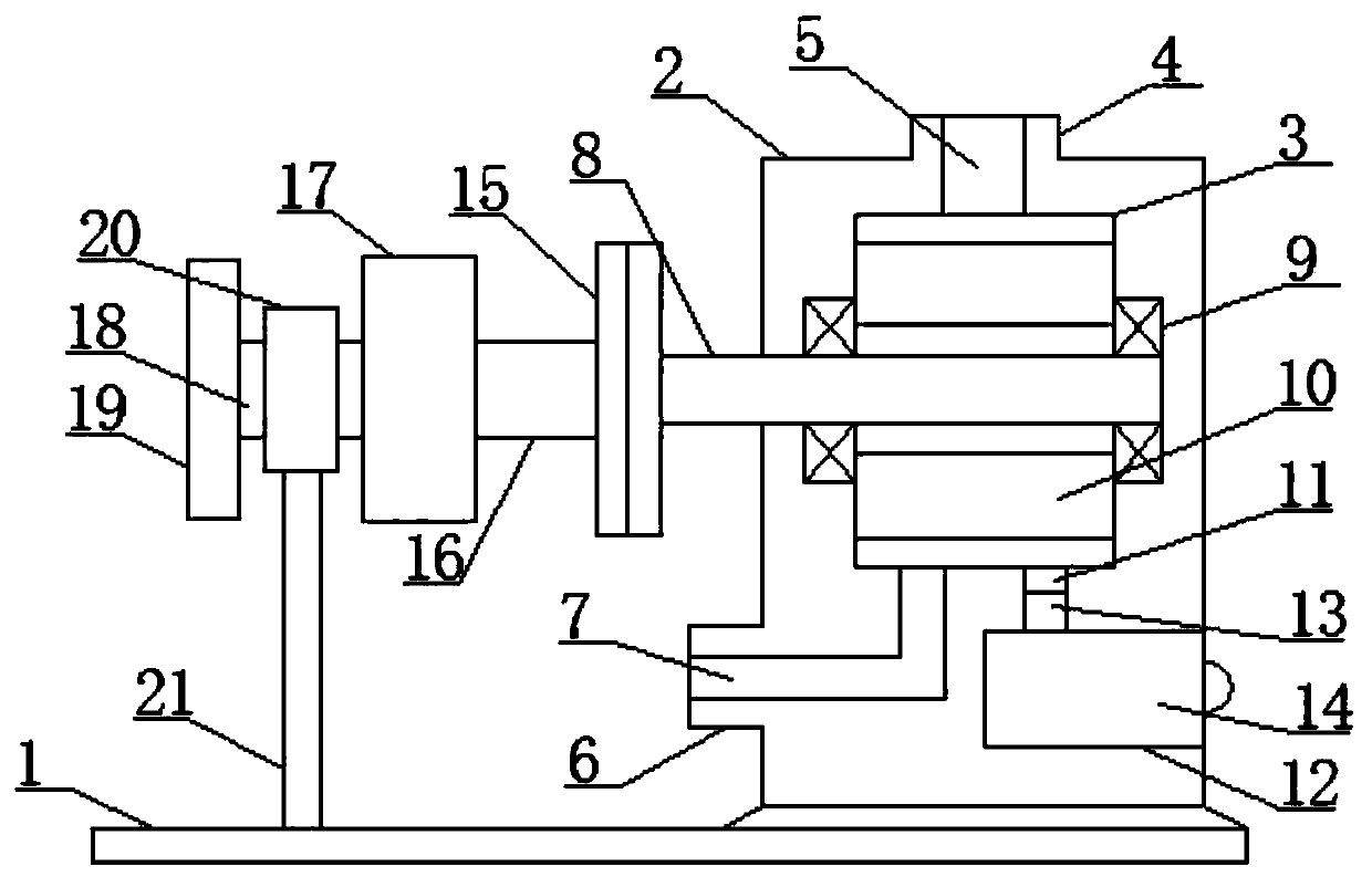
[0021] see figure 1 , an embodiment provided by the present invention: includes a bottom mounting substrate 1, one side of the upper surface of the bottom mounting substrate 1 is provided with a main hollow casing 2 with an integrated structure, and the center of the main hollow casing 2 is provided with a turbine In the installation space 3, the top of the main hollow shell 2 is provided with a main liquid inlet pipe 4 with an integral structure...
PUM
 Abstract
Description
Claims
Application Information