Locking oil cylinder

A technology for locking oil cylinders and cylinder bodies, which is applied in the direction of fluid pressure actuating devices, etc., can solve the problems of large occupied space, increased oil circuits, and the accuracy cannot meet the requirements, and achieves low processing and manufacturing costs, ingenious conception, and simple structure. Effect

Inactive Publication Date: 2020-07-10
邵延荣
View PDF0 Cites 3 Cited by
  • Summary
  • Abstract
  • Description
  • Claims
  • Application Information

AI Technical Summary

Problems solved by technology

At present, when the hydraulic lock is kept in a certain position for a long time, the accuracy often cannot meet the requirements due to pressure oil leakage and other problems. When an oil circuit failure occurs, the accuracy and reliability cannot be guaranteed; hydraulic locks often require one-way Valve, reversing valve and other auxiliary components cooperate to realize the locking circuit. The use of these components makes the whole device take up a lot of space. At the same time, the increase in the oil circuit is prone to leakage, causing inconvenience in maintenance and use.

Method used


Image

  • Locking oil cylinder
  • Locking oil cylinder
  • Locking oil cylinder

Examples


Embodiment Construction

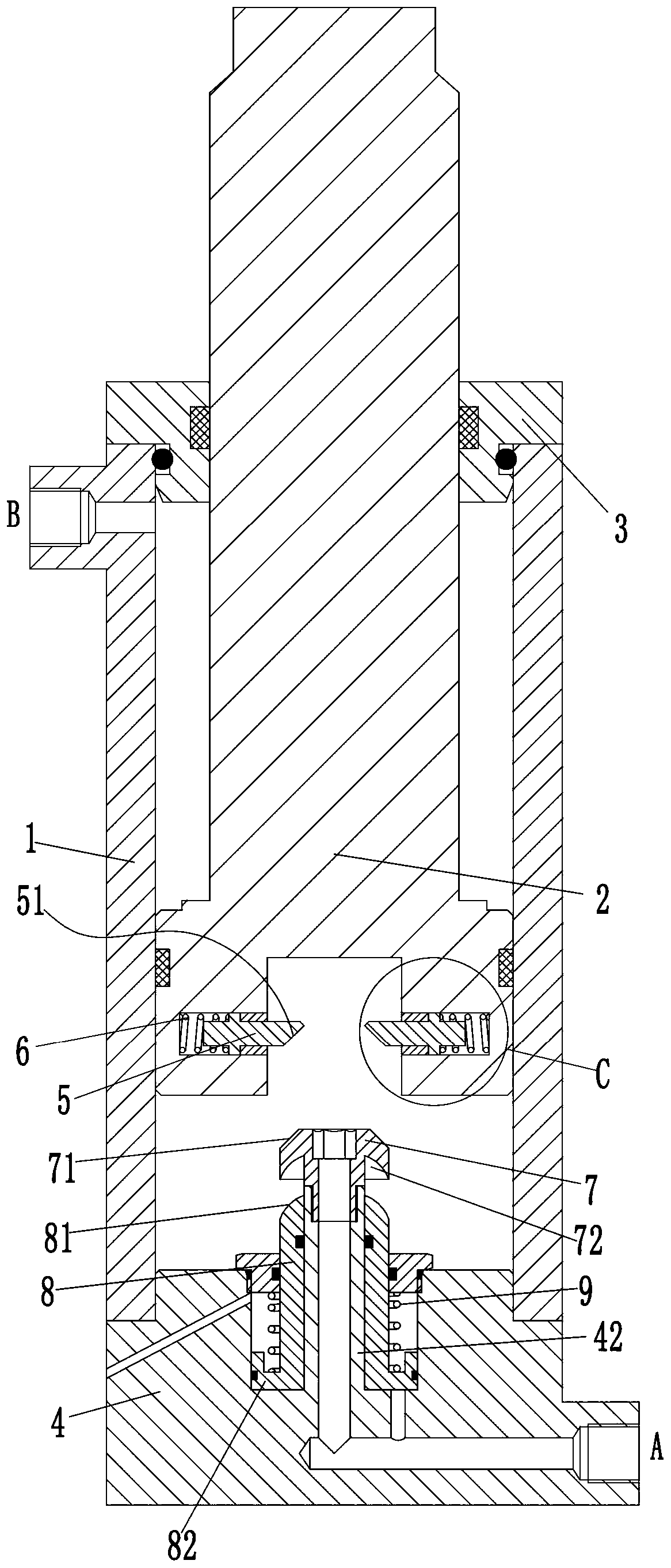
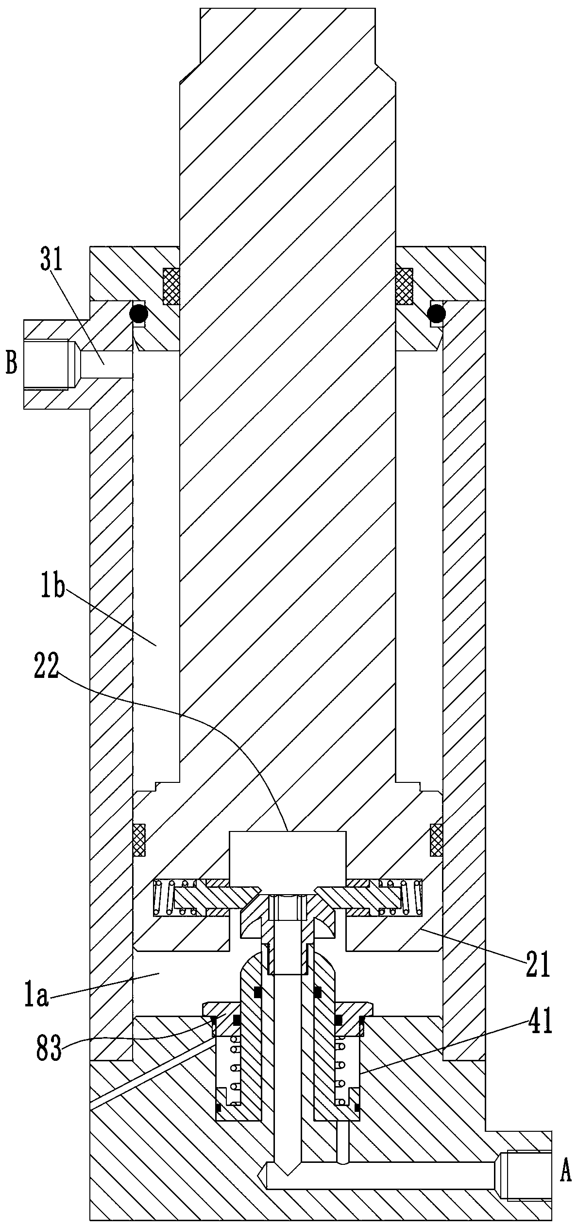
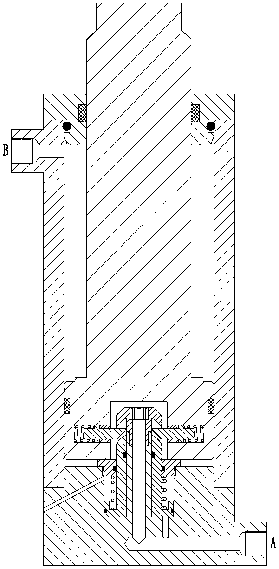
[0017] See Figure 1-5 As shown, a locking oil cylinder includes a cylinder body 1, an upper end cover 3 is provided at the upper end of the cylinder body 1, and a lower end cover 4 is provided at the lower end; a piston body 21 is slidably connected in the vertical direction in the cylinder body 1 The upper end of the piston body 21 is vertically provided with a piston rod 2 extending from the upper end cover 3; a rodless cavity 1a is formed in the cylinder body 1 between the piston body 21 and the lower end cover 4. A rod cavity 1b is formed between the upper end cover 3 and the upper end cover 3; the side of the lower end cover 4 is provided with an A port communicating with the rodless cavity 1a, the side of the cylinder 1 is provided with a B port, and the cylinder 1 is provided with There is an upper through hole 31 for connecting the rod cavity 1b and the B port; the lower end cover 4 is vertically downwardly provided with a mounting groove 41 communicating with the rodl...


PUM


Abstract

The invention discloses a locking oil cylinder. The locking oil cylinder comprises a cylinder body. An upper end cover is arranged at the upper end of the cylinder body, and a lower end cover is arranged at the lower end of the cylinder body. A piston body is slidably connected in the cylinder body in the vertical direction, and a piston rod extending out of the upper end cover is arranged at theupper end of the piston body in the vertical direction. A rodless cavity is formed between the piston body and the lower end cover in the cylinder body, and a rod cavity is formed between the piston body and the upper end cover. A port A communicated with the rodless cavity is formed in the side face of the lower end cover, and a port B communicated with the rod cavity is formed in the side face of the cylinder body. A mounting groove communicated with the rodless cavity is formed in the lower end cover in the vertical direction, a locking rod extending vertically is arranged at the center ofthe bottom of the mounting groove, and a locking block is fixedly mounted at the upper end of the locking rod. A locking groove is formed in the lower end of the piston body. A locking assembly is arranged in the locking groove. An unlocking assembly is arranged in the lower end cover. The locking oil cylinder is simple in structure and capable of automatically locking and unlocking the piston body.

Description

Technical field [0001] The invention belongs to the technical field of oil cylinders, and specifically relates to a locking oil cylinder. Background technique [0002] Self-locking hydraulic cylinders are widely required in the mechanical fields of many take-off and landing equipment such as metallurgy and coal mines. In order to prevent the workpiece from being displaced under the action of external force or self-weight (hydraulic cylinder vertical placement) when the work is stopped, hydraulic components need to be The hydraulic cylinder is locked. At present, when the hydraulic lock is kept in a certain position for a long time, the accuracy is often not up to the requirements due to problems such as pressure oil leakage. In the event of an oil circuit failure, the accuracy and reliability cannot be guaranteed; hydraulic locks often require one-way A number of auxiliary components such as valves and reversing valves cooperate to achieve the locking circuit. The use of these c...

Claims


Application Information

Patent Timeline
Patent Type & Authority Applications(China)
IPC IPC(8): F15B15/14F15B15/26
CPCF15B15/1423F15B15/1447F15B15/149F15B15/261F15B2015/268
Inventor 邵延荣其他发明人请求不公开姓名
Owner 邵延荣
Why Eureka
Try Eureka