Separable butterfly-shaped leading-in optical cable assembly and optical cable stripping method based on separable butterfly-shaped leading-in optical cable assembly

An introduction and separation technology for optical cables, applied in the field of optical cable manufacturing, can solve problems such as damage, limited use of pipeline space, and poor protection performance of optical cables, and achieve the effect of improving new mechanical energy.

Pending Publication Date: 2020-07-10
FURUKAWA ELECTRIC XIAN OPTICAL COMM
View PDF0 Cites 1 Cited by
  • Summary
  • Abstract
  • Description
  • Claims
  • Application Information

AI Technical Summary

Problems solved by technology

[0002] The current butterfly-shaped drop cable is mainly used for indoor fiber-to-the-home introduction, but some cables may be laid through pipes during the lead-in process, but the space in the pipe is limited, so the only way to further reduce the size of the cable and its installation in the pipe The friction force can ensure the smooth laying in the pipeline
However, directly reducing the size of the optical cable will deteriorate the protection performance of the optical cable laid outside the duct, and there may be a risk of being damaged, thereby affecting the transmission performance of the optical fiber in the cable

Method used


Image

  • Separable butterfly-shaped leading-in optical cable assembly and optical cable stripping method based on separable butterfly-shaped leading-in optical cable assembly
  • Separable butterfly-shaped leading-in optical cable assembly and optical cable stripping method based on separable butterfly-shaped leading-in optical cable assembly
  • Separable butterfly-shaped leading-in optical cable assembly and optical cable stripping method based on separable butterfly-shaped leading-in optical cable assembly

Examples


Embodiment Construction

[0035] The present invention will be further described in detail below in conjunction with specific embodiments, which are explanations of the present invention rather than limitations.

[0036] The invention discloses a detachable butterfly lead-in optical cable assembly, which comprises an optical cable body and an optical cable stripping device for stripping the optical cable body.

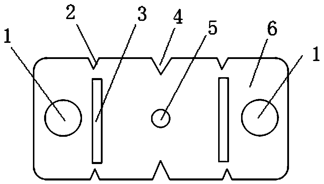
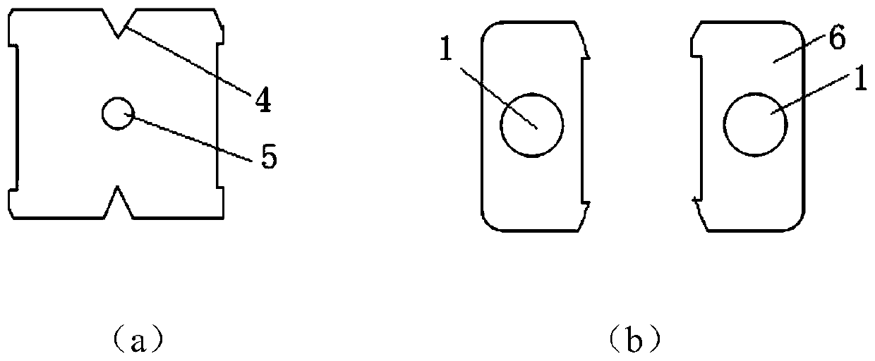
[0037] like figure 1 As shown, the present invention discloses a detachable butterfly-shaped lead-in optical cable, which includes an optical cable body. The optical cable body includes an optical cable strengthening member 1, an optical fiber 5 and an outer sheath 6. The optical cable strengthening member 1 is symmetrically arranged on both sides of the optical fiber 5, and the outer sheath The sheath 6 is wrapped around the optical fiber 5 and the fiber optic cable strength member 1, and an optical fiber tearing groove 4 is opened on the outer sheath 6 corresponding to the upper and lower sid...


PUM


Abstract

The invention discloses a separable butterfly-shaped leading-in optical cable assembly which comprises an optical cable body and an optical cable stripping device used for stripping the optical cablebody. The optical cable body comprises an optical cable reinforcer, an optical fiber and an outer sheath, separation gaps are formed in the outer sheath and located on the left side and the right sideof the optical fiber, and optical cable separation grooves are formed in the portions, corresponding to the upper side and the lower side of each separation gap, of the outer sheath respectively; theoptical cable stripping device comprises a shell, an upper cutter and a lower cutter are installed in the shell, and when the optical cable stripping device is used, the distance between the two upper cutters and the distance between the two lower cutters are matched with the distance between the optical cable separating grooves. A through hole is formed in the other side of the shell; during stripping, the optical cable passes through the through hole, the optical cable separating groove is ensured to be just located at the position of the cutter, and then when the cutter and the optical cable move relatively, the optical cable can be smoothly separated, cut and separated to form an optical fiber-containing part and two reinforcer-containing parts so that the size of the optical cable isreduced, and the optical cable is convenient to lay in the pipeline without influencing the transmission performance of the optical fibers in the optical cable.

Description

technical field [0001] The invention belongs to the field of optical cable manufacturing, and relates to a detachable butterfly-shaped lead-in optical cable assembly and an optical cable stripping method based on it. Background technique [0002] The current butterfly-shaped drop cable is mainly used for indoor fiber-to-the-home introduction, but some cables may be laid through pipes during the lead-in process, but the space in the pipe is limited, so the only way to further reduce the size of the cable and its installation in the pipe The friction force can ensure the smooth laying in the pipeline. However, directly reducing the size of the optical cable will deteriorate the protection performance of the optical cable laid outside the duct, and there may be a risk of being damaged, thereby affecting the transmission performance of the optical fiber in the optical cable. In this context, it is necessary to develop a new type of butterfly-shaped drop cable, which can reduce ...

Claims


Application Information

Patent Timeline
IPC IPC(8): G02B6/44
CPCG02B6/567
Inventor 刘少锋张彬张义军朱勇刘胜县张乐龚博樊轩虎
Owner FURUKAWA ELECTRIC XIAN OPTICAL COMM
Why Eureka
Try Eureka