LED screen power supply control device and method

A power control device and LED screen technology, applied in the circuit field, can solve the problems of LED screen waste of electric energy, etc., and achieve the effect of solving waste of electric energy and reducing standby power consumption

Inactive Publication Date: 2020-07-10
UNILUMIN GRP
View PDF7 Cites 2 Cited by
  • Summary
  • Abstract
  • Description
  • Claims
  • Application Information

AI Technical Summary

Problems solved by technology

[0003] This article is to provide a LED screen power control device and method, by adding a control circuit in the box to control the on-off of the switch device, reducing the standby power consumption of the LED screen, and solving the problem of wasting power when the LED screen is idle

Method used


Image

  • LED screen power supply control device and method
  • LED screen power supply control device and method
  • LED screen power supply control device and method

Examples


Embodiment 1

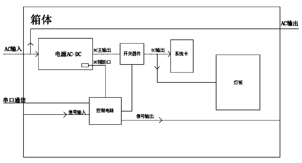
[0025] Such as figure 1 As shown, in this embodiment, a LED screen power control device includes: a box body and a power supply, a system card and an LED lamp board arranged in the box body, and the box body is also provided with: a control circuit and a switch device, The switch device is arranged at the output end of the power supply, and is used to control the power on and off of the system card and the LED light board; the control circuit is connected to the switch device, and is used to control the power of the switch device. on and off.

[0026] In this embodiment, by adding a control circuit in the box to control the on-off of the switch device, the standby power consumption of the LED screen is reduced, and the problem of wasting electric energy when the LED screen is idle is solved.

[0027] In this embodiment, the power supply accepts AC input and generates DC main output and DC auxiliary output. The output voltage is the same but the current is smaller. It was ori...

Embodiment 2

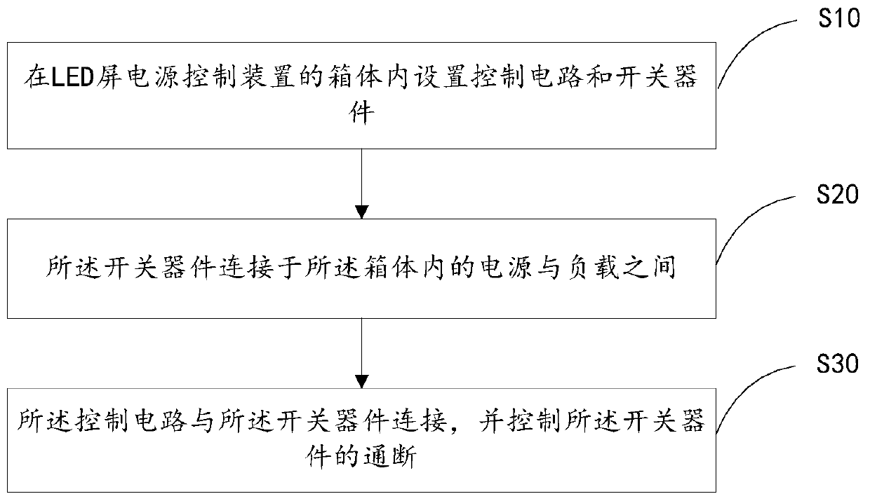
[0037] Such as image 3As shown, in this embodiment, a LED screen power control method includes:

[0038] S10, a control circuit and a switching device are arranged in the box of the LED screen power supply control device;

[0039] S20. The switching device is connected between the power supply and the load in the box;

[0040] S30. The control circuit is connected to the switch device, and controls the switch device to be turned on and off.

[0041] In this embodiment, by adding a control circuit in the box to control the on-off of the switch device, the standby power consumption of the LED screen is reduced, and the problem of wasting electric energy when the LED screen is idle is solved.

[0042] In this embodiment, the power supply accepts AC input and generates DC main output and DC auxiliary output. The output voltage is the same but the current is smaller. It was originally used to detect whether the power supply failed. Now we connect it to the control circuit. The...


PUM


Abstract

The invention discloses an LED screen power supply control device and method and belongs to the technical field of circuits. The LED screen power supply control device comprises a box body, a power supply, a system card and an LED lamp panel, wherein the power supply, the system card and the LED lamp panel are arranged in the box body, a control circuit and a switching device are also arranged inthe box body, and the switching device is arranged at the output end of the power supply and used for controlling the on-off of the system card and the LED lamp panel; the control circuit is connectedwith the switching device and is used for controlling the on-off of the switching device; by adding the control circuit in the box body, the on-off of the switching device is controlled, the standbypower consumption of the LED screen is reduced, and the problem that electric energy is wasted when the LED screen is idle is solved.

Description

technical field [0001] This article relates to the field of circuit technology, in particular to an LED screen power control device and method. Background technique [0002] Usually, a complete LED cabinet consists of the following parts: cabinet, power supply, system card, adapter board and module. The current LED large screen magic technology is generally relatively simple for the control of electric energy. The wires are directly drawn from the power distribution cabinet, connected to the air switch and then entered into the screen. As a protection device, the air switch will not be turned off manually, so when the large-screen display is not needed, since the power supply is always present, although the LED lamp beads basically have no power consumption at this time, other parts of the cabinet such as The system card and driver IC are still in the working state, resulting in a single box with a black LED screen that also consumes tens of watts of power consumption. At t...

Claims


Application Information

Patent Timeline
Patent Type & Authority Applications(China)
IPC IPC(8): G09G3/32
CPCG09G3/32G09G2330/021
Inventor 王金山雷松
Owner UNILUMIN GRP
Why Eureka
Try Eureka