
Dimming circuit needing no distinguishing of input and output and lighting system

An input-output, dimming circuit technology, applied in the field of dimming, can solve the problems of danger, non-compliance with safety regulations, intelligent dimming switch live wire and load wire wrong connection, etc., to achieve low cost, avoid malfunction, structure simple effect

Pending Publication Date: 2020-07-10
LEEDARSON IOT TECH INC
View PDF0 Cites 2 Cited by
  • Summary
  • Abstract
  • Description
  • Claims
  • Application Information

AI Technical Summary

Problems solved by technology

[0003] In view of this, the embodiment of the present invention provides a dimming circuit and a lighting system that do not need to distinguish between input and output, so as to solve the problem that the live wire and the load wire are often connected incorrectly in the traditional intelligent dimming switch, which does not meet the requirements of safety regulations, causing certain the dangerous problem

Method used


Image

  • Dimming circuit needing no distinguishing of input and output and lighting system
  • Dimming circuit needing no distinguishing of input and output and lighting system
  • Dimming circuit needing no distinguishing of input and output and lighting system

Examples


Embodiment Construction

[0042] In the following description, specific details such as specific system structures and technologies are presented for the purpose of illustration rather than limitation, so as to thoroughly understand the embodiments of the present invention. It will be apparent, however, to one skilled in the art that the invention may be practiced in other embodiments without these specific details. In other instances, detailed descriptions of well-known systems, devices, and methods are omitted so as not to obscure the description of the present invention with unnecessary detail.

[0043] In order to illustrate the technical solutions of the present invention, specific examples are used below to illustrate.

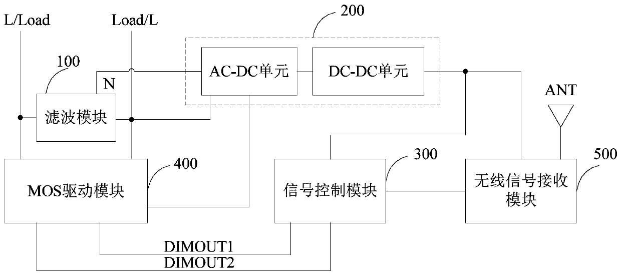
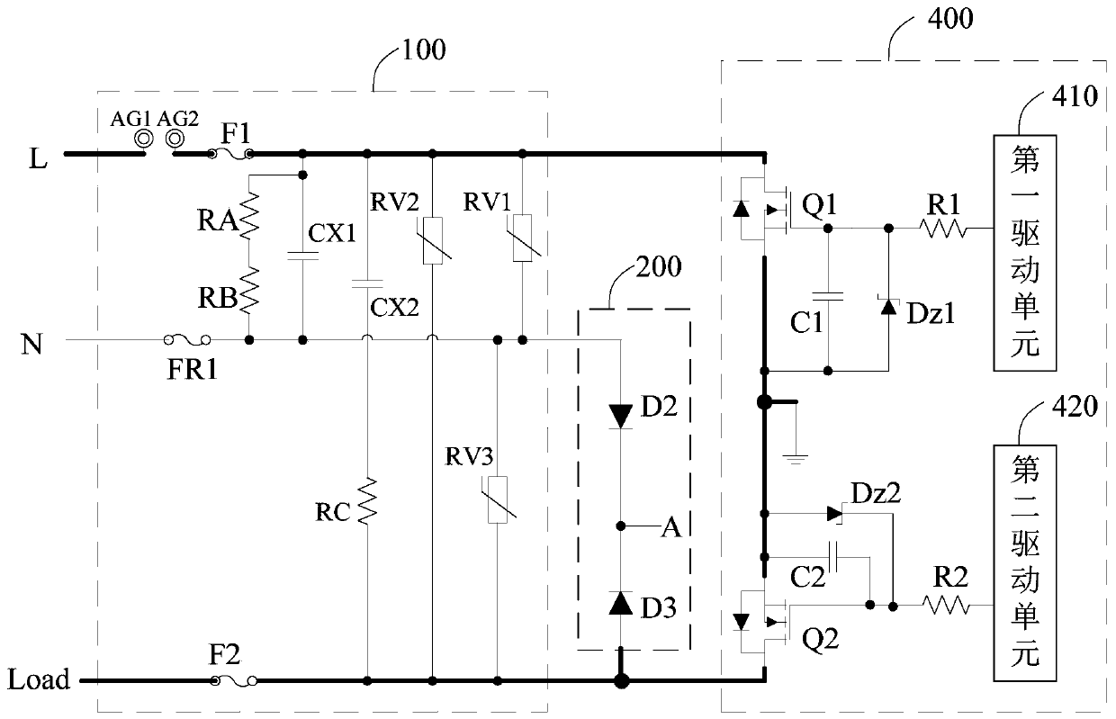
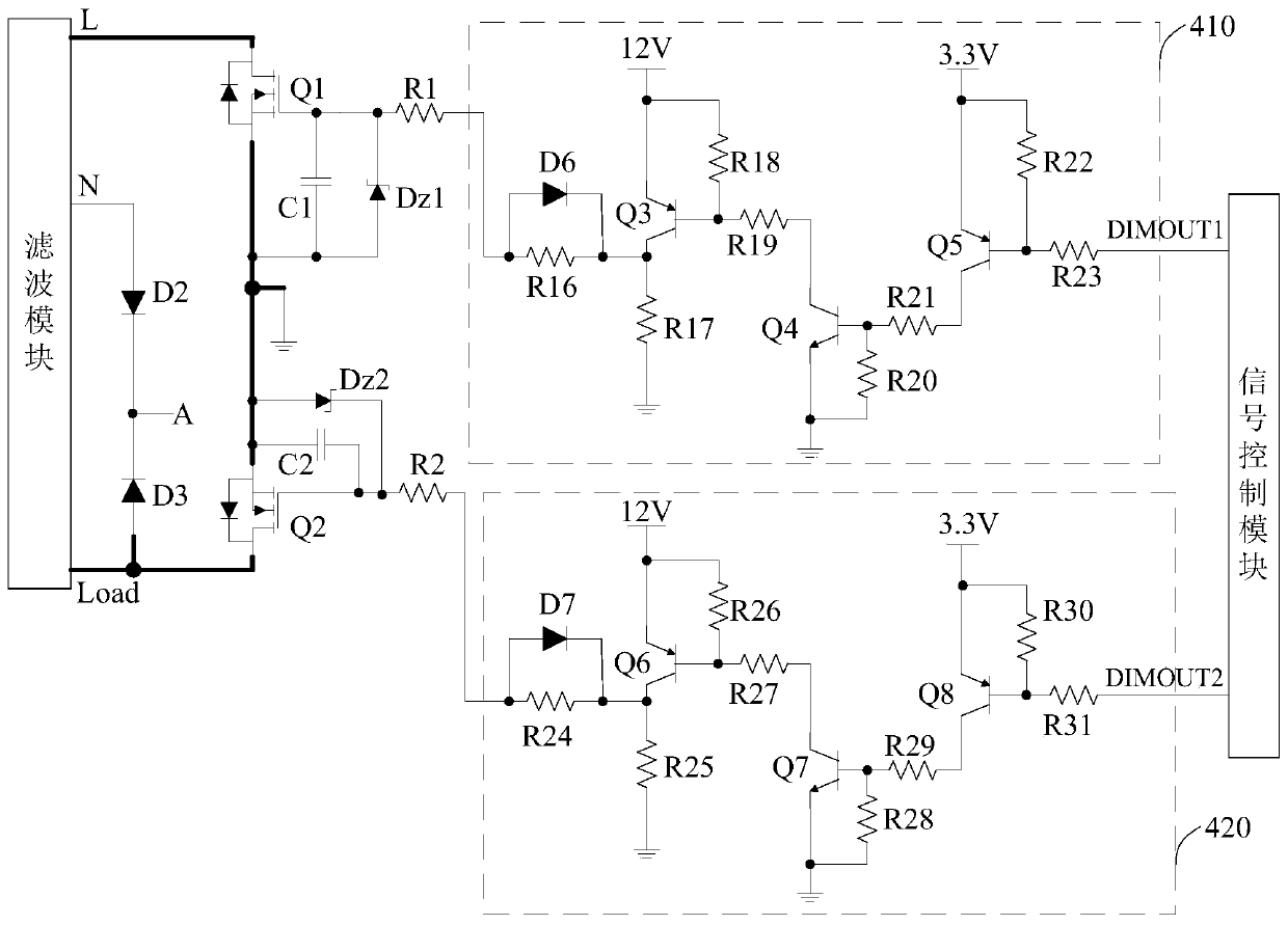
[0044] see figure 1 , the dimming circuit provided in this embodiment without distinguishing between input and output mainly includes: a filtering module 100 , a rectifying module 200 , a signal control module 300 and a MOS driving module 400 .

[0045] The first end of the fil...


PUM


Abstract

The invention is applicable to the technical field of dimming, and provides a dimming circuit needing no distinguishing of input and output and a lighting system. The dimming circuit comprises a filtering module, a rectifying module, a signal control module and an MOS driving module. The rectifying module supplies power to the signal control module and the MOS driving module. When a first end of the filtering module is connected with a live wire and a third end of the filtering module is connected with a lamp, the signal control module sends a first dimming signal to the MOS driving module according to user input, and the MOS driving module outputs a dimming voltage to the third end of the filtering module according to the first dimming signal. When the first end of the filtering module isconnected with the lamp and the third end of the filtering module is connected with the live wire, the signal control module sends a second dimming signal to the MOS driving module, and the MOS driving module outputs a dimming voltage to the first end of the filtering module according to the second dimming signal. According to the invention, single-zero- / live-wire compatibility is realized, the live wire and the load wire do not need to be distinguished, the dimming circuit can work under random wiring, the operation is convenient, and the problem that normal work cannot be realized due to wrong wiring is avoided.

Description

technical field [0001] The invention belongs to the technical field of dimming, and in particular relates to a dimming circuit and a lighting system without distinguishing between input and output. Background technique [0002] Smart dimmer switches play an important role in smart homes, especially in hotels. When using smart dimmer switches, there are strict wiring requirements, but traditional smart dimmer switches often have misconnection of live wires and load wires (wires connected to lamps), which do not meet safety requirements and cause certain dangers. Contents of the invention [0003] In view of this, the embodiment of the present invention provides a dimming circuit and a lighting system that do not need to distinguish between input and output, so as to solve the problem that the live wire and the load wire are often connected incorrectly in the traditional intelligent dimming switch, which does not meet the requirements of safety regulations, causing certain ...

Claims


Application Information

Patent Timeline
Patent Type & Authority Applications(China)
IPC IPC(8): H05B45/34H05B45/10
Inventor 黄延峰庄佳卿肖海鹏
Owner LEEDARSON IOT TECH INC
Learn More