A convenient disassembly and assembly pan-tilt mounting mechanism for multi-rotor drones

A technology for the mounting and installation mechanism of a multi-rotor UAV with a gimbal, which is applied to structural parts, power units, aircraft parts, etc. The effect of installation stability, improving structure compactness and reasonable structure configuration

Active Publication Date: 2021-06-22
厦门致睿智控地信科技股份有限公司
View PDF6 Cites 0 Cited by
  • Summary
  • Abstract
  • Description
  • Claims
  • Application Information

AI Technical Summary

Problems solved by technology

First, the motor of the rotor UAV tends to generate relatively large vibrations during operation. During the flight, the vibration generated by the motor is easily transmitted directly to the camera through the camera mounting mechanism, resulting in camera installation stability and aerial photography. The stability of the rotor drone is damaged; secondly, the body weight of the rotor UAV equipped with batteries will be greatly increased, resulting in a huge difference in the weight of the camera mounting mechanism and the rotor UAV body, resulting in the rotor being unmanned during the aerial photography flight. There is a huge difference in the inertial potential energy between the body of the aircraft and the camera, which will easily further lead to insufficient stability of the camera installation and aerial photography.
It not only improves the driving difficulty of the rotor drone, but also reduces the applicability of the rotor drone

Method used


Image

  • A convenient disassembly and assembly pan-tilt mounting mechanism for multi-rotor drones
  • A convenient disassembly and assembly pan-tilt mounting mechanism for multi-rotor drones
  • A convenient disassembly and assembly pan-tilt mounting mechanism for multi-rotor drones

Examples


Embodiment Construction

[0027] In order to facilitate the understanding of those skilled in the art, the structure of the present invention will be further described in detail with the embodiments in conjunction with the accompanying drawings:

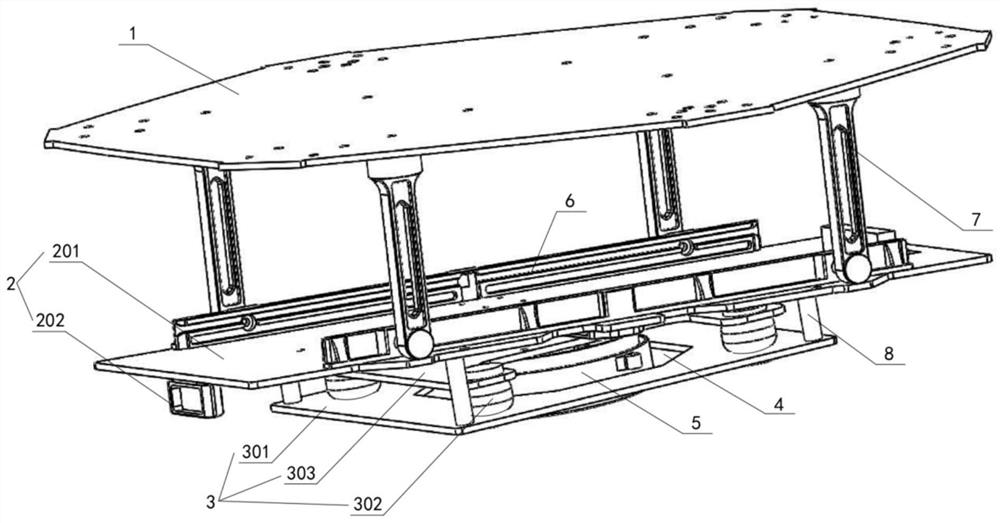
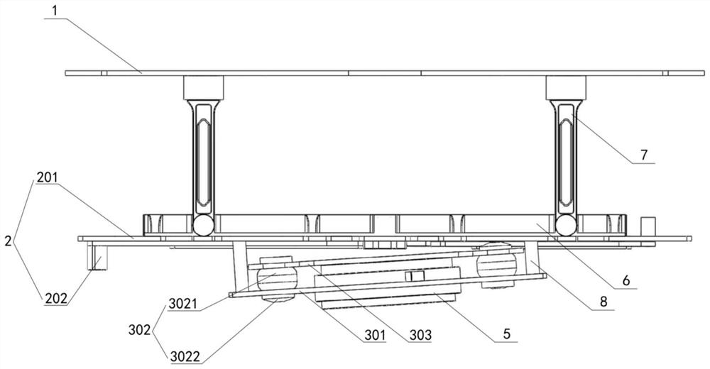
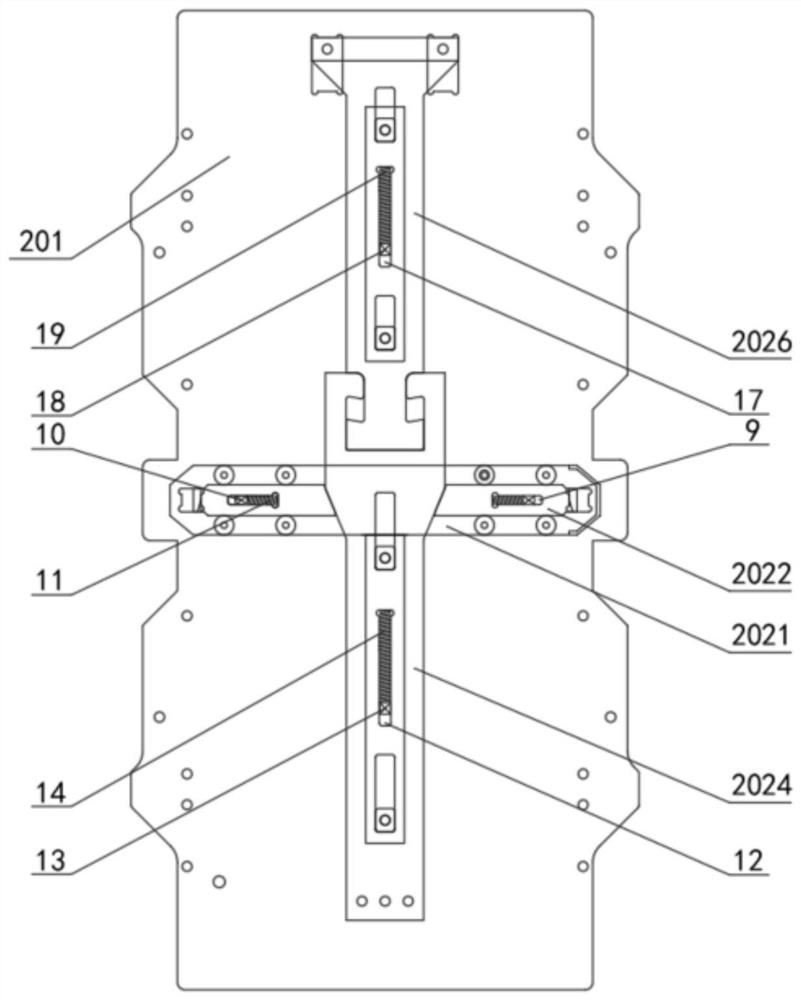
[0028] refer to Figure 1-6, a multi-rotor unmanned aerial vehicle with easy disassembly and assembly of the pan-tilt mounting mechanism, including a connecting plate 1, a battery mounting mechanism 2 and a camera mounting mechanism 3, the battery mounting mechanism 2 includes a connecting plate connected to the connecting plate 1 The battery mounting plate 201 is provided with a pullable battery mounting mechanism 202; the camera mounting mechanism 3 includes a camera mounting plate 301 fixed under the battery mounting plate 201, and the camera mounting The center of the plate 301 is provided with a corresponding through hole 4, and the camera mounting plate 301 is evenly fixed with a plurality of corresponding elastic connectors 302 along the periphery of t...


PUM


Abstract

The invention relates to a multi-rotor unmanned aerial vehicle with a convenient disassembly and assembly pan-tilt mounting mechanism, which includes a connecting plate, a battery mounting mechanism and a camera mounting mechanism, and the battery mounting mechanism includes a battery mounting plate connected to the connecting plate , the battery mounting plate is provided with a pullable battery mounting mechanism; the camera mounting mechanism includes a camera mounting plate fixed under the battery mounting plate, and the center of the camera mounting plate is provided with a corresponding through hole, the camera mounting plate is evenly fixed with a plurality of corresponding elastic connectors along the periphery of the through hole, the top of the elastic connectors is fixed with a camera mounting plate, and the camera mounting plate is fixed downwards with a penetrating device The camera connection mechanism through the hole. The invention can not only effectively reduce the difficulty of disassembling and assembling the battery, but also can effectively reduce the driving difficulty of the rotor drone and improve the applicability of the rotor drone.

Description

technical field [0001] The invention relates to a pan-tilt mounting mechanism for a multi-rotor UAV, in particular to a pan-tilt mounting mechanism for a multi-rotor UAV that is easy to assemble and disassemble. Background technique [0002] The rotor UAV has the characteristics of small size, light weight, low cost, flexible operation and high safety. It is equipped with multiple propellers, and the flight is realized by controlling multiple propellers through multiple motors. Rotor UAVs are widely used in aerial photography, detection, search and rescue, resource exploration, agriculture and other fields. [0003] Existing batteries for rotor drones generally have a relatively large weight. In order to ensure stable installation, the batteries for rotor drones are usually installed directly on the body of the rotor drone in a detachable manner. In order to ensure the stable installation of the battery, the body of the existing rotor drone is generally provided with a batt...

Claims


Application Information

Patent Timeline
Patent Type & Authority Patents(China)
IPC IPC(8): B64D27/24B60K1/04B64D47/08H01M50/244H01M50/249H01M50/264
CPCB60K1/04B64D27/24B64D47/08H01M2220/20H01M50/20Y02E60/10
Inventor 陈阳杨伟李震灏
Owner 厦门致睿智控地信科技股份有限公司
Why Eureka
Try Eureka