Thread end processing device for winding machine

A technology of a processing device and a wire take-up machine, which is applied in the field of wire head processing devices and can solve problems such as increased labor costs

Pending Publication Date: 2020-07-14
苏州梅塔摩尔通信科技有限公司
View PDF0 Cites 0 Cited by
  • Summary
  • Abstract
  • Description
  • Claims
  • Application Information

AI Technical Summary

Problems solved by technology

However, the current removal of thread ends is all manual operation, so ...

Method used


Image

  • Thread end processing device for winding machine
  • Thread end processing device for winding machine
  • Thread end processing device for winding machine

Examples


Embodiment Construction

[0025] The present invention will be described in further detail below through specific examples.

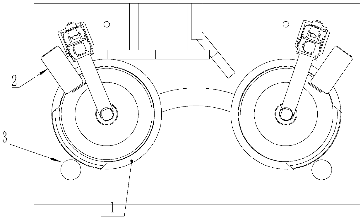
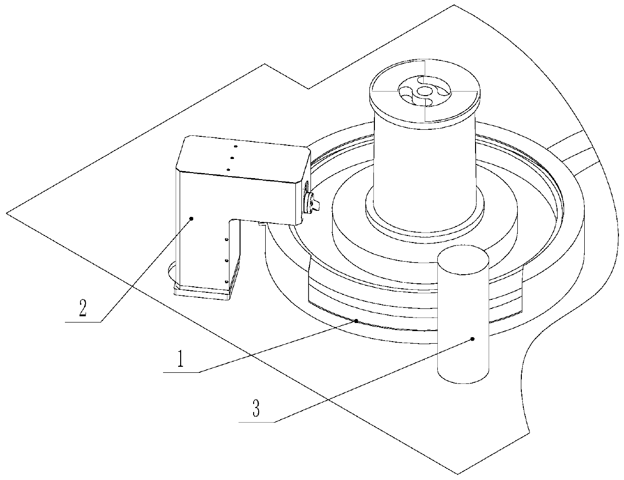
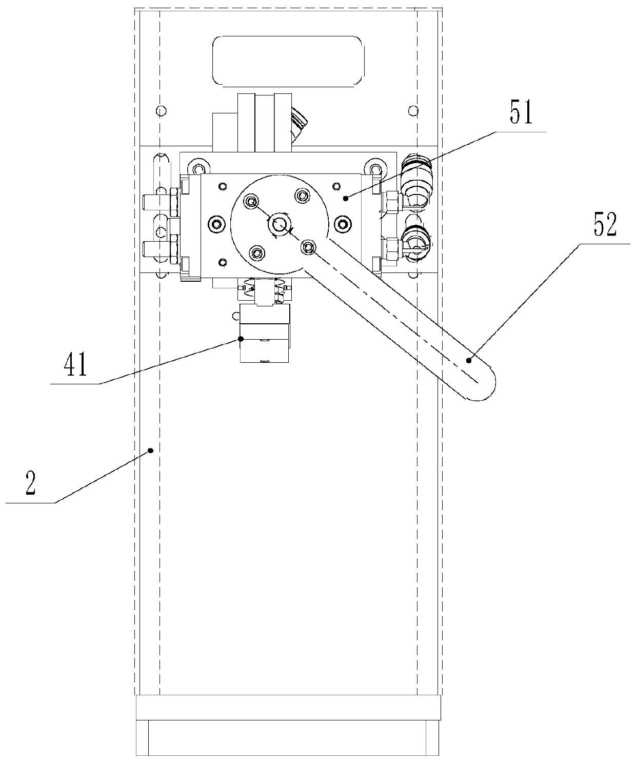
[0026] Such as Figure 1 to Figure 4 As shown, a thread end processing device of a wire take-up machine includes a base 2 arranged on the side of the rotating disk 1 of the wire take-up machine, and an unclamp mechanism 4 is installed on the base 2, and the unclamp mechanism 4 includes a slidingly installed The unclamping pressing block 41 driven by the unclamping power device 42, the side of the rotating disc 1 is installed with a thread end clamp addressing device that drives the rotating disc 1 to rotate, and the thread end clamp addressing device drives the rotating disc 1 to stay at the position of unclamping The station makes the end of thread clip on the rotary disk 1 adapt to the position of the clamping block 41, and the end of thread is also installed on the base 2 to remove the end of thread mechanism 5 from the end of thread clip.

[0027] The wire take-up machine i...


PUM


Abstract

The invention discloses a thread end processing device for a winding machine. The thread end processing device comprises a base arranged on the side surface of a rotating disc of the winding machine,wherein a clamp opening mechanism is installed on the base, the clamp opening mechanism comprises a clamp opening pressing block slidably installed on the base and driven by a clamp opening power device, a thread end clamp addressing device for driving the rotating disc to rotate is installed on the side surface of the rotating disc, and the thread end clamp addressing device drives the rotating disc to stay at a clamp opening station, so that a thread end clamp on the rotating disc is matched with the clamp opening pressing block position, and a thread end pulling-away mechanism for pulling away a thread end from the thread end clamp is further installed on the base. According to the thread end processing device, the thread end clamp can be automatically opened to pull away the thread end, so that the manual work is replaced, and the labor cost is reduced.

Description

technical field [0001] The invention relates to a thread end processing device, in particular to a thread end processing device used on a wire take-up machine. Background technique [0002] The wire take-up machine is a device that winds the wire bundle on the wire reel. The take-up machine generally includes a rotating disk, which is driven by the take-up power device. The wire harness is unwound and passed through the transition wheel and then wound on the wire reel through the wire arrangement mechanism. The wire reel is placed on the rotation of the take-up machine On the disk, then the power transmission is realized between the wire disk and the rotating disk through the cooperation of the clamping block and the groove. The wire end of the wire harness needs to be wound on the wire end clamp of the rotating disc, so that the wire harness can be completely wound on the wire reel, and after the wire reel is full of wire harnesses, the wire end clamp needs to be opened, a...

Claims


Application Information

Patent Timeline
IPC IPC(8): B65H75/28B65H75/18
CPCB65H75/18B65H75/285
Inventor 赵亮
Owner 苏州梅塔摩尔通信科技有限公司
Why Eureka
Try Eureka