
High beam and low beam integrated vehicle headlamp

A technology for far and near beams and headlights, applied in the field of lighting, can solve the problems of reducing service life, reducing the utilization rate of light energy and lighting effect, and limiting the thickness of heat dissipation substrates.

Pending Publication Date: 2020-07-14
苏州晶清光电科技有限公司
View PDF0 Cites 4 Cited by
  • Summary
  • Abstract
  • Description
  • Claims
  • Application Information

AI Technical Summary

Problems solved by technology

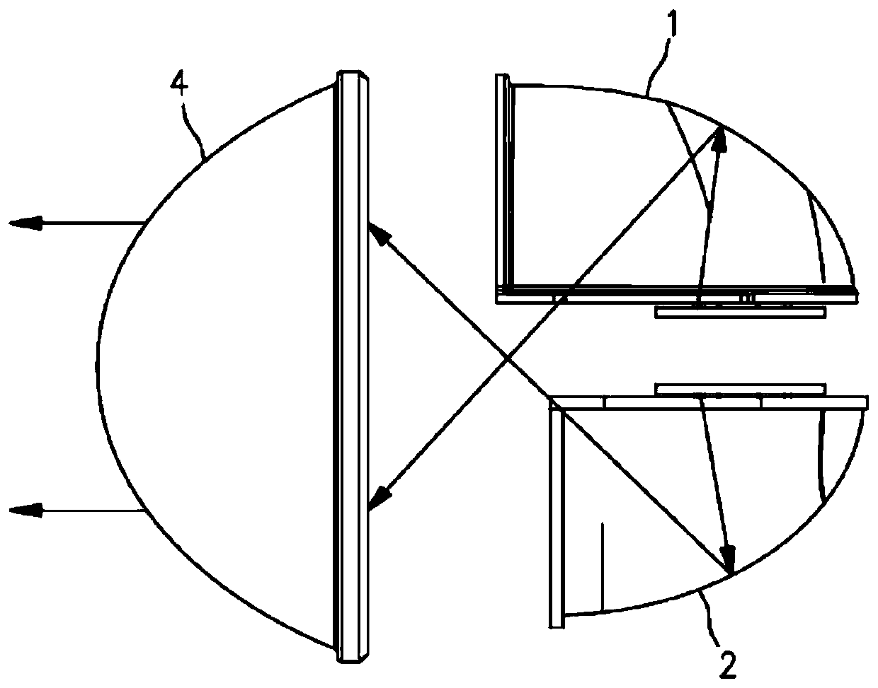
The low-beam LED light source module 1 and the high-beam LED light source module 2 are arranged on the upper and lower sides of the same heat dissipation substrate, and the positions of the low-beam LED light source module 1 and the high-beam LED light source module 2 on both sides of the heat dissipation substrate are basically They overlap or are very close together, so the heat dissipation surfaces of the two LED light sources are parallel to each other and attached to the same heat dissipation substrate, so the heat dissipation channels of the two LEDs overlap, which seriously affects the heat dissipation effect of the system
In addition, in order to improve light collection efficiency, the distance between the high and low beam LED light source modules in the vertical direction should not be too large, resulting in the limitation of the thickness of the heat dissipation substrate between the high and low beam LED light source modules, which also affects the heat dissipation of the headlights The effect will eventually lead to an increase in the temperature of the lamp and reduce its service life
In addition, since the LED light source has a certain thickness (usually 1-2 mm), and there is a space in the middle for the heat dissipation substrate, there must be a large distance between the light-emitting surfaces of the two light source modules (usually 1-2mm). 5-7mm), resulting in a large system volume
In addition, due to the large distance between the light-emitting surfaces of the two light source modules, there is no light or less light in the middle area of ​​the lens 4, and the brightness of the formed lighting spot is uneven, which reduces the light energy utilization rate and lighting effect.

Method used


Image

  • High beam and low beam integrated vehicle headlamp
  • High beam and low beam integrated vehicle headlamp
  • High beam and low beam integrated vehicle headlamp

Examples


Embodiment Construction

[0022] The present invention is described in detail below in conjunction with accompanying drawing:

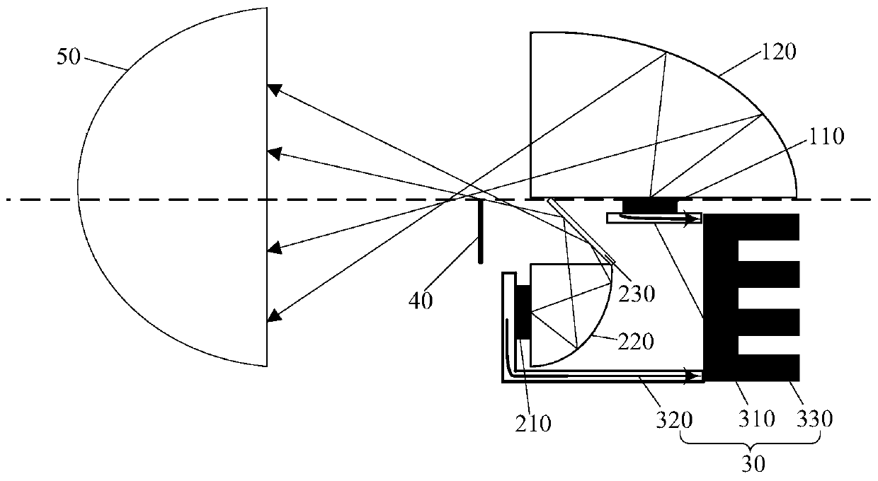
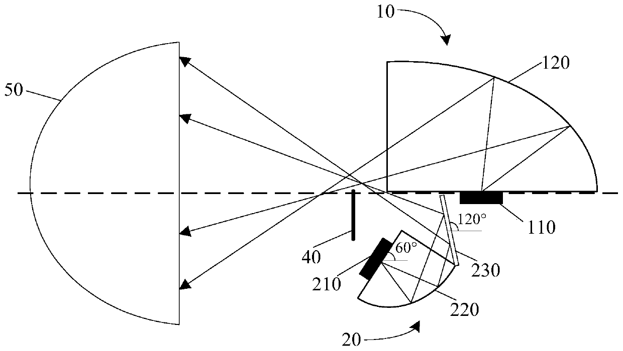
[0023] Such as Figure 2-3 As shown, the present invention provides a vehicle headlamp with integrated far and near beams, including a low beam module 10, a high beam module 20 and a heat dissipation module 30 located below the low beam module 10, and a heat dissipation module 30 located in sequence. The visor 40 and the lens 50 in front of the low beam module 10 and the high beam module 20, the low beam module 10 includes a low beam LED light source 110, and a low beam reflective cup 120 corresponding to the low beam LED light source 110 The high beam module 20 includes a high beam LED light source 210, a high beam reflective cup 220 corresponding to the high beam LED light source 210, and a reflector 230 corresponding to the light outlet of the high beam reflective cup 220, the The height of the top of the reflector 230 corresponds to the height of the light-emitting surfac...


PUM


Abstract

The invention discloses a high beam and low beam integrated vehicle headlamp. The vehicle headlamp comprises a low-beam module, a high-beam module and a heat dissipation module which are located belowthe low-beam module, and a shading plate and a lens, wherein the shading plate and the lens are sequentially located in front of the low-beam module and the high-beam module. The low-beam module comprises a low-beam LED light source and a low-beam reflection cup corresponding to the low-beam LED light source. The high-beam module comprises a high-beam LED light source, a high-beam reflection cupcorresponding to the high-beam LED light source and a reflector corresponding to the light emitting port of the high-beam reflection cup, the height of the top of the reflector corresponds to the height of the light-emitting face of the low-beam LED light source, and light emitted by the high-beam LED light source is projected to the reflector after being collected by the high-beam reflection cupand is projected to the lens after being reflected by the reflector. The distance between the light-emitting surface of the low-beam LED light source and the light-emitting surface of the high-beam LED light source is reduced, the size of the system is reduced, and the lighting effect and the light energy utilization rate of the whole system are effectively improved.

Description

technical field [0001] The invention relates to the field of lighting technology, in particular to a vehicle headlamp with integrated far and near beams. Background technique [0002] The structure of the existing LED far and near light integrated automobile headlights is as follows: figure 1 As shown, it includes a low-beam LED light source module 1 , a high-beam LED light source module 2 and a lens 4 . The low-beam LED light source module 1 and the high-beam LED light source module 2 are arranged on the upper and lower sides of the same heat dissipation substrate, and the positions of the low-beam LED light source module 1 and the high-beam LED light source module 2 on both sides of the heat dissipation substrate are basically They overlap or are very close to each other, so the heat dissipation surfaces of the two LED light sources are parallel to each other, and they are attached to the same heat dissipation substrate, so the heat dissipation channels of the two LEDs ov...

Claims


Application Information

Patent Timeline
IPC IPC(8): F21S41/141F21S41/16F21S41/33F21S45/48F21W102/13F21W107/10F21Y113/20F21Y115/10F21Y115/30
CPCF21S41/141F21S41/16F21S41/337F21S45/48F21W2102/13F21W2107/10F21Y2113/20F21Y2115/10F21Y2115/30
Inventor 邹诚许明
Owner 苏州晶清光电科技有限公司
Learn More