High-precision water level measuring device of water level gauge

A high-precision technology for water level measurement, applied in the field of water level meters, can solve the problems of low accuracy of measurement results, and achieve the effects of improved display accuracy, convenient use, and high measurement accuracy

Active Publication Date: 2020-07-14
江苏鑫亚达仪表制造有限公司
View PDF12 Cites 0 Cited by
  • Summary
  • Abstract
  • Description
  • Claims
  • Application Information

AI Technical Summary

Problems solved by technology

[0002] The water level gauge is a measuring device used to detect the water level inside the boiler. Due to temperature changes, the pressure inside the boiler is always changing. The existing water level gauge cannot make timely adjustments when measuring the water level inside the boiler. , resulting in inaccurate measurement results

Method used


Image

  • High-precision water level measuring device of water level gauge
  • High-precision water level measuring device of water level gauge
  • High-precision water level measuring device of water level gauge

Examples


Embodiment 1

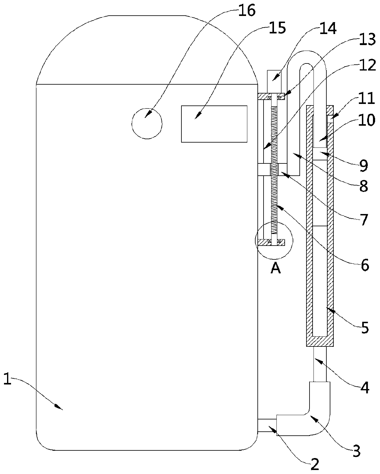
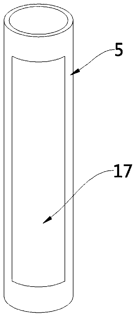
[0023] see Figure 1-2 , this embodiment provides a high-precision water level measuring device for a water level meter, including a display tube 5 arranged on one side of the furnace body 1 and forming a communication structure with the furnace body 1, and an observation tube is provided on the side wall of the display tube 5 A second pressure gauge (not shown) for detecting the internal pressure of the display cylinder 5 is provided outside the display cylinder 5, a display glass 17 is provided at the observation port, and a second pressure gauge (not shown) for detecting the internal pressure of the furnace body 1 is installed on the furnace body 1. The first pressure gauge 16 of the internal pressure and the controller 15 electrically connected with the pressure gauge 16, the pressure compensating assembly is installed on the upper part of the display tube 5, specifically, the pressure compensating assembly includes a movable setting on the display The pressure plate 9 ins...

Embodiment 2

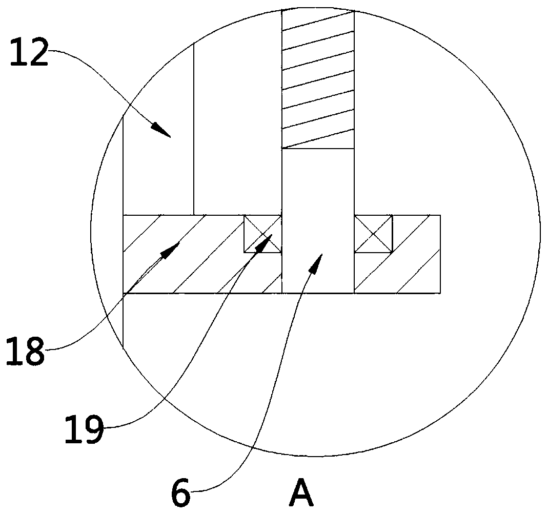
[0036] see figure 1 and image 3, a high-precision water level measuring device for a water level meter. Compared with Embodiment 1, the side wall of the furnace body 1 is also fixedly provided with a second support plate 18, and the drive shaft 6 is far away from the end of the motor 14. It is rotationally matched with the second support plate 18 through a bearing 19 .

[0037] The embodiment of the present invention has the advantages of convenient use and high measurement accuracy. The liquid level of the furnace body 1 can be measured accurately in real time according to the pressure change inside the furnace body 1. The first drive rod 8, The second drive rod 10 and the pressing plate 9 move up and down, thereby increasing or decreasing the pressure inside the display cylinder 5, so that the pressure inside the display cylinder 5 and the furnace body 1 are always equal, ensuring that the liquid level inside the display cylinder 5 is equal to that of the furnace body 1. ...


PUM


Abstract

The invention provides a high-precision water level measuring device of a water level gauge and belongs to the technical field of water level indicators. The device comprises a display cylinder arranged on one side of a furnace body and forming a communicating vessel structure with the furnace body, an observation port is formed in the side wall of the display cylinder, a second pressure gauge used for detecting the internal pressure of the display cylinder is arranged outside the display cylinder, and display glass is arranged at the observation port. The device disclosed in an embodiment ofthe invention has the advantages of convenience in use and high measurement precision; the liquid level of the furnace body can be accurately measured in real time according to the pressure change inthe furnace body; the driving assembly is controlled by the controller to drive the first driving rod, the second driving rod and the pressing plate to move up and down, so that the pressure in the display cylinder is increased or reduced, the pressure in the display cylinder is always equal to that in the furnace body, the liquid level in the display cylinder is equal to that in the furnace body,and the display precision of the display cylinder is improved.

Description

technical field [0001] The invention belongs to the technical field of water level meters, in particular to a high-precision water level measuring device for water level meters. Background technique [0002] The water level gauge is a measuring device used to detect the water level inside the boiler. Due to temperature changes, the pressure inside the boiler is always changing. The existing water level gauge cannot make timely adjustments when measuring the water level inside the boiler. , resulting in inaccurate measurement results. Contents of the invention [0003] In view of the deficiencies in the prior art above, the technical problem to be solved by the embodiments of the present invention is to provide a high-precision water level measuring device for a water level gauge. [0004] In order to solve the problems of the technologies described above, the present invention provides the following technical solutions: [0005] A high-precision water level measuring dev...

Claims


Application Information

Patent Timeline
Patent Type & Authority Applications(China)
IPC IPC(8): G01F23/14
CPCG01F23/14
Inventor 张咏
Owner 江苏鑫亚达仪表制造有限公司
Why Eureka
Try Eureka