Method for interpreting seismic horizon to sedimentary unit in dense well network area
A technique for sedimentary units and seismic layers, which is applied in seismology, seismology, seismic signal processing, etc. for well logging records. It can solve the problems of sedimentary unit reservoir prediction, low efficiency, inability to obtain seismic data, and heavy horizon calibration workload. and other issues to achieve the effect of improving work efficiency and reducing labor intensity
- Summary
- Abstract
- Description
- Claims
- Application Information
AI Technical Summary
Problems solved by technology
Method used
Image

Examples
Embodiment 1
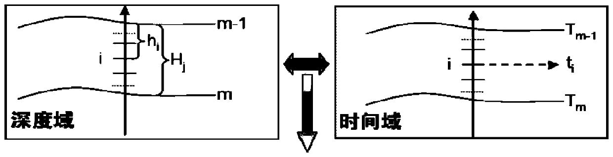
[0035] Taking the isochronous framework PI and GI of the oil layer group level in the BRX block of Changyuan Oilfield as an example, the method of interpreting the seismic horizon to the sedimentary unit in the dense well pattern area of the present invention is specifically explained
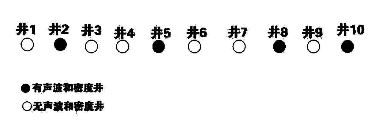
[0036] Such as figure 2 As shown, taking the 10 wells in the work area as an example, 4 wells have sound wave and density curves, and synthetic records can be made; the other 6 wells have no sound wave and density curves, so synthetic records cannot be made.
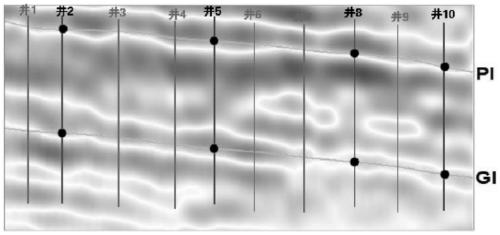
[0037] 1. With reference to the time-domain data of 4 wells for synthetic recording (Table 1 is the layered data of oil layer groups), the seismic reflection events corresponding to PI and GI on the top surface of oil layer groups can be tracked in the whole area (such as image 3 shown), under its control, the time values of the other 6 wells can be read out on the seismic section.
[0038] The overall stratigraphic thickness of PI...
PUM
 Abstract
Description
Claims
Application Information
 - Generate Ideas
- Intellectual Property
- Life Sciences
- Materials
- Tech Scout
- Unparalleled Data Quality
- Higher Quality Content
- 60% Fewer Hallucinations
Browse by: Latest US Patents, China's latest patents, Technical Efficacy Thesaurus, Application Domain, Technology Topic, Popular Technical Reports.
© 2025 PatSnap. All rights reserved.Legal|Privacy policy|Modern Slavery Act Transparency Statement|Sitemap|About US| Contact US: help@patsnap.com