Wire harness fixing device for high-temperature surface and application thereof
A wire harness fixing device and high-temperature technology, which is applied in the direction of transportation and packaging, electrical components, circuits or fluid pipelines, etc., can solve the problems affecting the fixing of wire harnesses, large contact area, complex structure, etc., and achieve small contact area, low cost, The effect of easy operation
- Summary
- Abstract
- Description
- Claims
- Application Information
AI Technical Summary
Problems solved by technology
Method used
Image
Examples
Embodiment 1
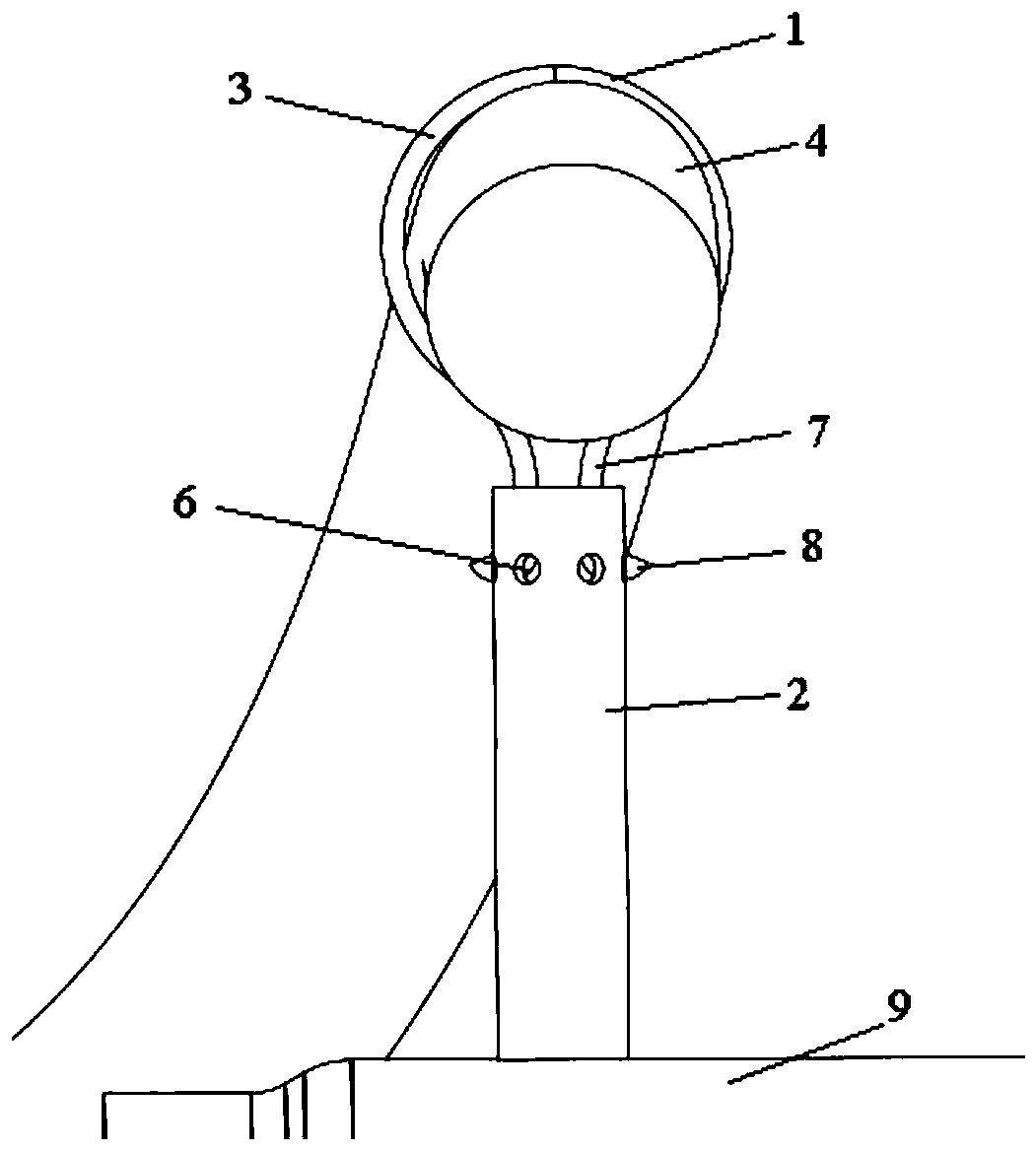
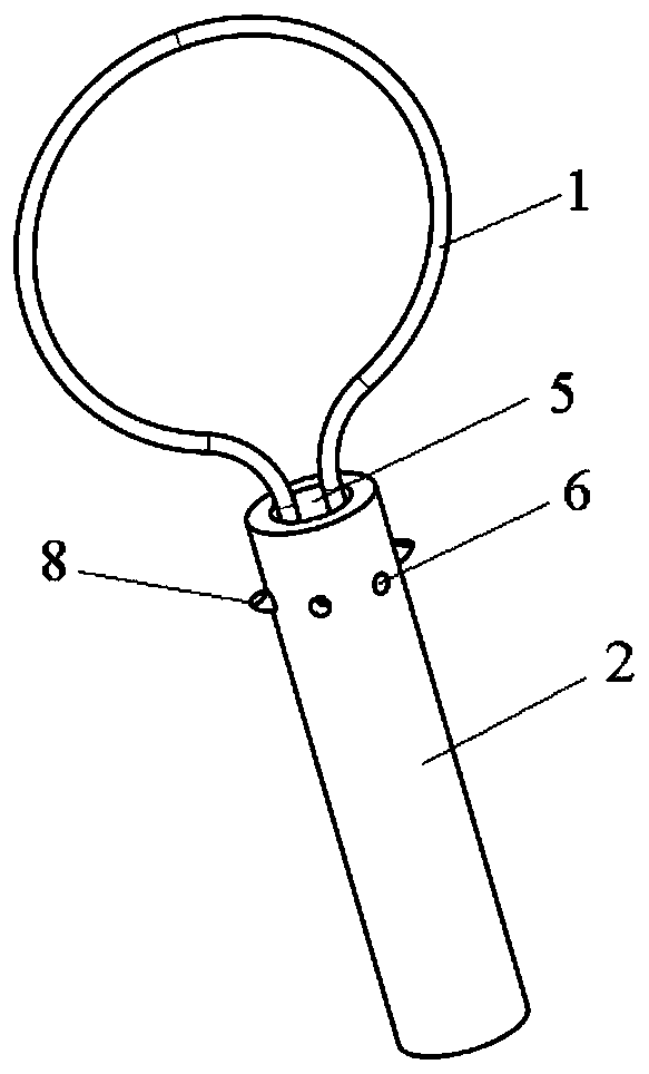
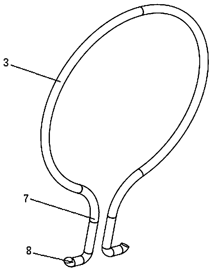
[0031] Such as figure 1 , figure 2 , image 3 As shown, the wire harness fixing device for high-temperature surfaces of the present invention includes a snap ring 1 and a pillar 2. The snap ring 1 is an opening structure, and the size of the opening can be elastically deformed within a certain range, thereby facilitating the passage of the wire harness 4. In, the snap ring 1 includes a ring part 3 to penetrate the wire harness 4 to be fixed, and the two ends of the opening of the ring part 3 are provided with root parts 7 to form the opening part of the snap ring 1, that is to say, the snap ring 1 is made of a profile It is bent and integrally formed, the pillar 2 is connected to the high-temperature surface 9, the top of the pillar 2 is provided with an inner insertion hole 5, and the upper circle of the pillar 2 is provided with a snap ring limit hole 6 communicating with the inner insertion hole 5; the cross section of the ring part 3 It is an arc larger than a semicircl...
Embodiment 2
[0036] Such as Figure 4 , Figure 5 As shown, there are two ring parts 3, and the opening ends on the same side of the two ring parts are connected to each other and share a root 7, that is, the snap ring 1 has a double-ring structure, and there is a gap between the two ring parts 3 , so as to enhance the binding ability of the clasp 1 to the wire harness 4; similarly, by external force acting on the roots 7 at both ends, the roots 7 and hooks 8 at both ends are relatively close together, and then the roots 7 extend into the inner insertion hole 5 , through the elastic force of the snap ring 1 itself, the hook portion 8 on the snap ring 1 is inserted into the stop hole 6 of the snap ring.
Embodiment 3
[0038] Such as Figure 6 , Figure 7 , Figure 10 As shown, the wire harness fixing device used on the high-temperature surface includes two independent snap rings 1, and there is a gap between the ring parts 3 of the two snap rings 1, so as to enhance the restraint ability of the wire harness 4; the snap ring 1 The root portions 7 are arranged adjacent to each other, that is, the inner insertion hole 5 can accommodate the tight root portions 7 of two snap rings 1; the inner diameter of the snap ring limiting hole 6 is not less than the overlapping width of the hook portions 8 of the two snap rings 1 ; In this embodiment, there are 4 snap ring limit holes 6, and they are set on the circumference of the pillar 2 symmetrically in pairs, and the roots 7 of the two independent snap rings 1 extend into the inner insertion hole 5 through external force , and the hooks 8 of the two snap rings 1 on the same side are all inserted into the same snap ring limiting hole 6 .
[0039] Th...
PUM
 Abstract
Description
Claims
Application Information
 - R&D
- Intellectual Property
- Life Sciences
- Materials
- Tech Scout
- Unparalleled Data Quality
- Higher Quality Content
- 60% Fewer Hallucinations
Browse by: Latest US Patents, China's latest patents, Technical Efficacy Thesaurus, Application Domain, Technology Topic, Popular Technical Reports.
© 2025 PatSnap. All rights reserved.Legal|Privacy policy|Modern Slavery Act Transparency Statement|Sitemap|About US| Contact US: help@patsnap.com


