Novel ankle joint rehabilitation parallel mechanism

A technology of ankle joints and parallel connection, which is applied in the direction of pivot connection, passive exercise equipment, physical therapy, etc., can solve the problems of difficult processing accuracy and loss of freedom, etc., and achieve low manufacturing processing accuracy, easy realization, and simple structure Effect

Pending Publication Date: 2020-07-17
HEBEI UNIV OF TECH
View PDF1 Cites 6 Cited by
  • Summary
  • Abstract
  • Description
  • Claims
  • Application Information

AI Technical Summary

Problems solved by technology

The intersection points of the axis lines of the holes at both ends of all A-type connecting rods connected to the moving platform are always coincident with the center of the moving ball, and the axis lines of the holes at both ends of all A-type connecting rods connected with the fixed platform are always coincident with the center of the fixed ball ; If there is an A-type connecting rod or B-type connecting rod of a branch chain or the assembly accuracy of the branch chain is not up to the requirements, it will cause the B-rod fixed ball center or moving ball center of all B-type connecting rods to not coincide, so that The whole mechanism loses the degree of freedom, so the manufacturing precision and assembly precision of the mechanism are required to be very high; since the binding force of each kinematic branch chain is calculated according to the spiral theory, each kinematic branch chain will provide a The binding force of the connecting line between the center and the center of the ball, so there will be two redundant constraints, that is, two virtual constraints; and to adjust the distance between the center of the fixed ball and the center of the moving ball, it is necessary to change the distance of each branch chain The rod length of the A-type connecting rod, the rod length of the B-type connecting rod and the length of the "double center line segment", the precise adjustment of the distance between the center of the fixed ball and the center of the moving ball is difficult to achieve in terms of machining accuracy.

Method used


Image

  • Novel ankle joint rehabilitation parallel mechanism
  • Novel ankle joint rehabilitation parallel mechanism
  • Novel ankle joint rehabilitation parallel mechanism

Examples


Embodiment 1

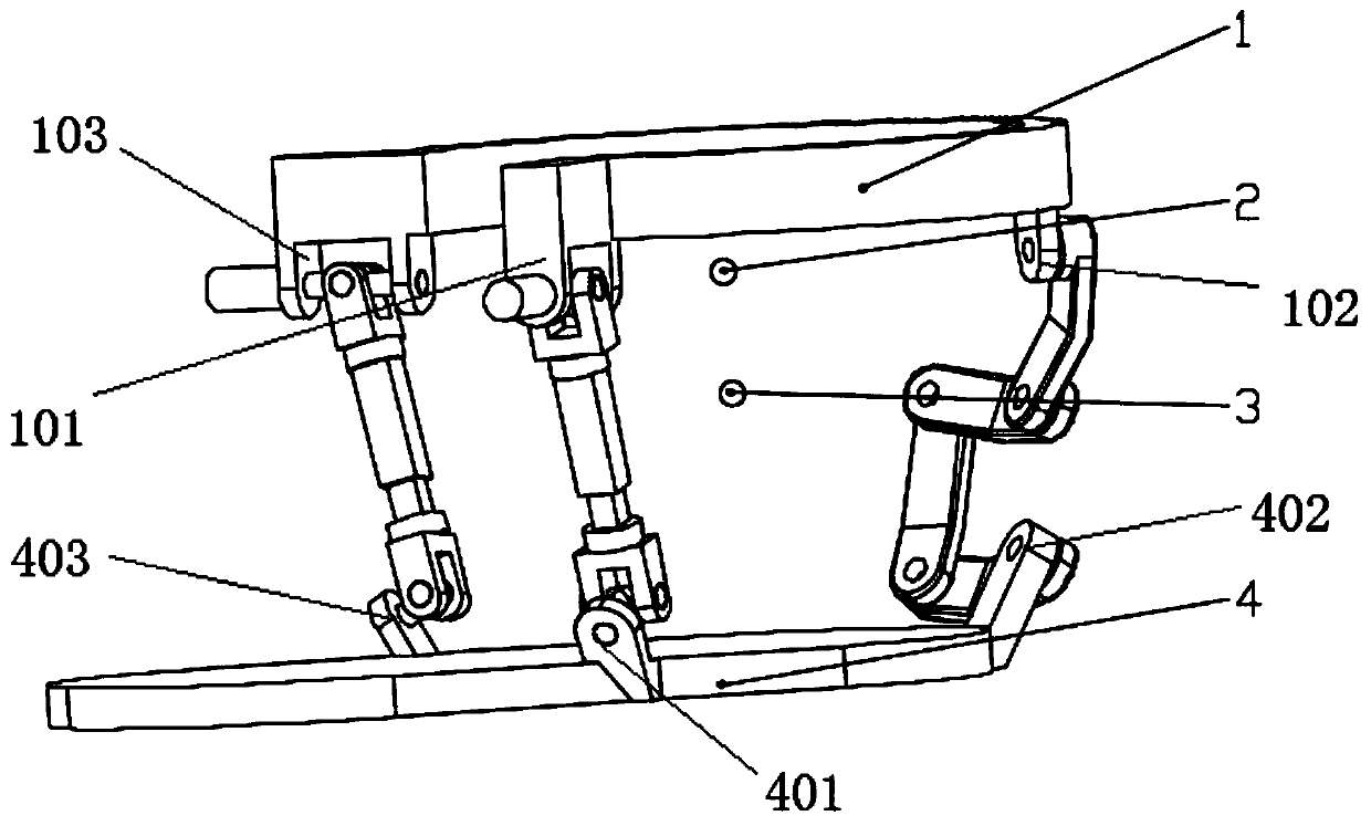
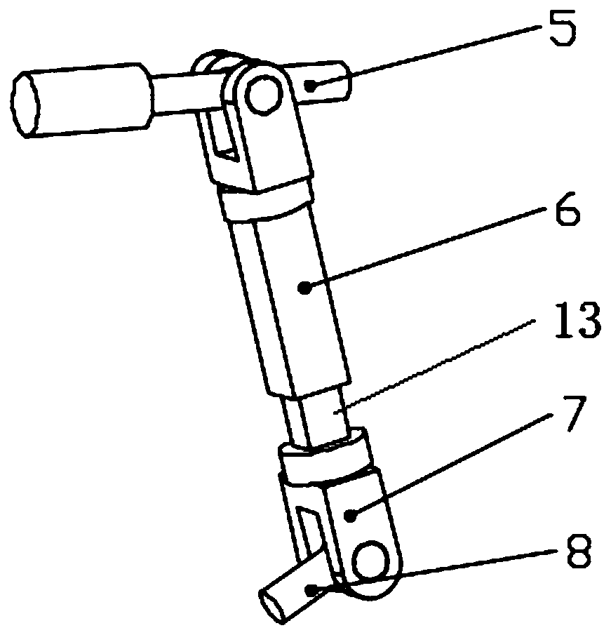
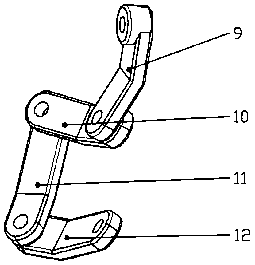
[0031] A kind of novel ankle joint rehabilitation parallel mechanism of this embodiment (referring to Figure 1-3 ), including static platform 1, dynamic platform 4, two UPU branch chains and one AABA branch chain;

[0032] The static platform 1 is evenly distributed on the circumference with the No. 1 hinge support 101 of the static platform, the No. 2 hinge support 102 of the static platform, and the No. 3 hinge support 103 of the static platform. The axes of the hinge holes of the three static platform hinge supports Converge at one point, this point is the fixed ball center 2 of the parallel mechanism;

[0033] On the moving platform 4, the No. 1 hinge support 401 of the moving platform, the No. 2 hinge support 402 of the moving platform and the No. 3 hinge support 403 of the moving platform are evenly distributed on the circumference, and the axes of the hinge holes of the three moving platform hinge supports Converge at one point, this point is the moving ball center 3 ...

Embodiment 2

[0042] A kind of novel ankle joint rehabilitation parallel mechanism of this embodiment (referring to Figure 1-3 ), including static platform 1, dynamic platform 4, two UPU branch chains and one AABA branch chain;

[0043] The static platform 1 is evenly distributed on the circumference with the No. 1 hinge support 101 of the static platform, the No. 2 hinge support 102 of the static platform, and the No. 3 hinge support 103 of the static platform. The axes of the hinge holes of the three static platform hinge supports Converge at one point, this point is the fixed ball center 2 of the parallel mechanism;

[0044] On the moving platform 4, the No. 1 hinge support 401 of the moving platform, the No. 2 hinge support 402 of the moving platform and the No. 3 hinge support 403 of the moving platform are evenly distributed on the circumference, and the axes of the hinge holes of the three moving platform hinge supports Converge at one point, this point is the moving ball center 3 ...


PUM


Abstract

The invention discloses a novel ankle joint rehabilitation parallel mechanism. The mechanism comprises a static platform, a movable platform, two UPU branched chains and an AABA-type branched chain; the parallel mechanism is provided with two non-coincident rotary spherical centers which are respectively a fixed spherical center and a movable spherical center; the whole parallel mechanism is regarded as that the movable spherical center performs spherical motion with two degrees of freedom around the fixed spherical center, and the movable platform performs spherical motion with one degree offreedom around the movable spherical center under the constraint of the three branched chains; rotation axes of rotary pairs respectively between the three branched chains and the static platform meetat a point which is the fixed spherical center of the parallel mechanism; rotation axes of rotary pairs respectively between the three branched chains and the movable platform meet at a point which is the movable spherical center of the parallel mechanism; each UPU branched chain is provided with a moving pair along the length direction of the UPU branched chain; the two UPU branched chains control the positions of the fixed spherical center and the movable spherical center in space; and a B-type connecting rod in the AABA-type branched chain controls the distance between the fixed sphericalcenter and the movable spherical center. The parallel mechanism has the advantages of lower manufacturing, processing and assembling precision, simpler and more compact structure and lower cost.

Description

technical field [0001] The invention relates to the field of mechanical engineering, in particular to a novel ankle joint rehabilitation parallel mechanism. Background technique [0002] The ankle joint is an important joint in the human body. It is an energy hub that supports the weight of the body and pushes the human body off the ground. At the same time, the ankle joint is also the joint that is most likely to be damaged due to body weight or external impact. As China's aging population and patients with hemiplegia intensify, the problem of ankle joint exercise rehabilitation is becoming more and more serious. With the development of sports rehabilitation theory and robotics technology, ankle joint rehabilitation robots have been produced, which can assist therapists in performing sports rehabilitation on patients' ankle joints. The movement of the ankle joint rehabilitation robot is stable and controllable, which can not only ensure the efficiency and intensity of trai...

Claims


Application Information

Patent Timeline
Patent Type & Authority Applications(China)
IPC IPC(8): A61H1/02F16C11/04
CPCA61H1/0266A61H2201/14A61H2201/1659A61H2205/12F16C11/04
Inventor 张建军杨帅刘承磊戚开诚牛建业郭士杰刘旭升刘秀莹
Owner HEBEI UNIV OF TECH
Why Eureka
Try Eureka