Motorcycle engine electrical starting structure

An engine, electric starting technology, applied in the direction of motor starting, engine starting, engine components, etc., can solve problems such as damage

Pending Publication Date: 2019-01-04
力帆科技(集团)股份有限公司
View PDF0 Cites 3 Cited by
  • Summary
  • Abstract
  • Description
  • Claims
  • Application Information

AI Technical Summary

Problems solved by technology

[0003] Aiming at the above-mentioned deficiencies in the prior art, the technical problem to be solved by the present invention is to provide an electric starter structure of the motorcycle engine, so as to avoid the parts in the electric starter structure caused by the recoil of the crankshaft when the electric starter fails or the engine is suddenly turned off during driving. The problem of damage is achieved, and the effect of effectively protecting the electric starter structure is achieved

Method used


Image

  • Motorcycle engine electrical starting structure
  • Motorcycle engine electrical starting structure
  • Motorcycle engine electrical starting structure

Examples


Embodiment 1

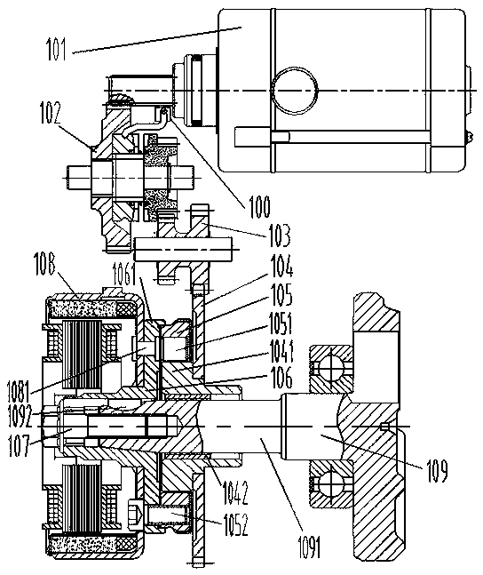
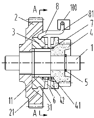
[0041] see Figure 1-3 , a kind of motorcycle engine electric starting structure of specific embodiment 1, comprise starter motor 101, described starter motor 101 is connected crankshaft 109 through transmission mechanism, and described transmission mechanism comprises big double gear 102, small double gear 103, clutch Start the gear 104 and the overrunning clutch 105, the large double gear 102 includes a rotating shaft 1, and the rotating shaft 1 is provided with a large gear 2, a transmission gear 3 and a pinion 4, and the large gear 2 and the rotating shaft 1 pass through a straight tooth flower key fit to ensure synchronous rotation, the pinion 4 is rotatable relative to the shaft 1, and a number of external helical splines 11 are processed on the section 1 of the shaft between the bull gear 2 and the pinion 4 to form an external helical spline section, so The transmission gear 3 is connected with the outer helical spline segment on the rotating shaft 1 through the corresp...

Embodiment 2

[0049] see figure 2 , 5 , The difference between the second embodiment and the first embodiment is that the return elastic mechanism and the elastic brake mechanism are set in different forms. The end face of the top is provided with a plug installation blind hole 32, and the plug installation blind hole 32 has a built-in spring 33. The corresponding position is the annular plane 43, and the end of the plug 34 facing the pinion 4 is higher than the end tooth 42 of the transmission gear 3 and abuts against the annular plane 43. In terms of positional relationship, the plug installation blind hole 32 and the annular plane 43 are respectively Located on the inner edge of the opposite end surfaces of the transmission gear 3 and the pinion gear 4 , the end surface teeth 42 are respectively located on the outer edges of the opposite end surfaces of the transmission gear 3 and the pinion gear 4 .

[0050] The elastic braking mechanism of the second embodiment is a spring piece 9, ...

Embodiment 3

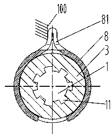
[0054] see figure 2 , 6 The difference between the third embodiment and the first embodiment is that the free end of the elastic section 81 is fixedly arranged, that is, it is fixedly connected with the assembled housing 100, because the axial movement stroke of the transmission gear 3 is not long, so You can also choose to fix the free end of the elastic section 81, so that the transmission gear 3 moves closer to the pinion 4, and when the helical compression spring is compressed, since the free end of the elastic section 81 is fixed, a certain amount of spring ring 8 will also occur. A certain amount of elastic deformation can also provide a certain return auxiliary force for the return of the transmission gear 3; of course, the fixing of the elastic coil 8 mainly restricts it from rotating with the transmission gear 3 to provide the necessary friction braking force.


PUM


Abstract

The invention relates to a motorcycle engine electrical starting structure comprising a starting motor. The starting motor is connected with a crankshaft through a large duplicate gear, a small duplicate gear, a clutch starting gear and an overrun clutch sequentially. The large duplicate gear comprises a rotary shaft. The rotary shaft is provided with a large gear, a transmission gear and a smallgear. The large gear and the rotary shaft rotate synchronously. The small gear can rotate relative to the rotary shaft. The transmission gear is in matched connection with a corresponding outer spiralspline section on the rotary shaft through an inner spiral spline groove and can move in the rotation direction of the outer spiral spline. The transmission gear is next to the small gear, and spaceis reserved between the transmission gear and the small gear in the axial direction, the opposite end faces of the transmission gear and the small gear are provided end face teeth which can mesh witheach other, and a return elastic mechanism is further arranged between the transmission gear and the small gear. An elastic rotation braking mechanism providing friction rotation braking force for thetransmission gear is further included. Normal electrical starting can be ensured, meanwhile when electrical starting fails or flameout occurs suddenly in the driving process, the conditions that thestarting motor and transmission parts are damaged by crankshaft reverse rotation and reverse impact can be prevented, and the electrical starting structure is protected effectively.

Description

technical field [0001] The invention belongs to the technical field of electric motor starting for motorcycle engines, and in particular relates to an electric starting structure for motorcycle engines. Background technique [0002] The original design of a motorcycle engine electric start structure is attached Figure 7 As shown, the starter motor 101 is sequentially connected to the crankshaft through a large double gear 102, a small double gear 103, etc., wherein the large double gear 102 includes an integral large gear 2 and a small gear 4, and cooperates with the rotating shaft 1 with a small clearance to be rotatable. When the starter motor 101 is electrically started, the gear on its output shaft drives the large gear 2 in the large double gear 102, and the pinion 4 in the large double gear 102 rotates and drives the small double gear 103 that is connected with it. Then drive the crankshaft by the small double gear 103 etc. to drive the engine to start electric. How...

Claims


Application Information

Patent Timeline
Patent Type & Authority Applications(China)
IPC IPC(8): F02N11/00F02N11/10F02N15/02
CPCF02N11/00F02N11/101F02N15/023
Inventor 王胜华
Owner 力帆科技(集团)股份有限公司
Why Eureka
Try Eureka