Dummy bar head seal system in a mould of a bar casting assembly for casting large-scale preliminary forms

A dummy rod and pre-shape technology, which is applied in the system field of sealing the dummy rod head, can solve problems such as being unsuitable for casting extra-large beam blanks, and achieve the effect of simplifying production

Inactive Publication Date: 2009-11-25
CONCAST AG
View PDF7 Cites 4 Cited by
  • Summary
  • Abstract
  • Description
  • Claims
  • Application Information

AI Technical Summary

Problems solved by technology

Therefore, the situation of the prior art system is not suitable for casting extra-large beam blanks

Method used


Image

  • Dummy bar head seal system in a mould of a bar casting assembly for casting large-scale preliminary forms
  • Dummy bar head seal system in a mould of a bar casting assembly for casting large-scale preliminary forms
  • Dummy bar head seal system in a mould of a bar casting assembly for casting large-scale preliminary forms

Examples


Embodiment Construction

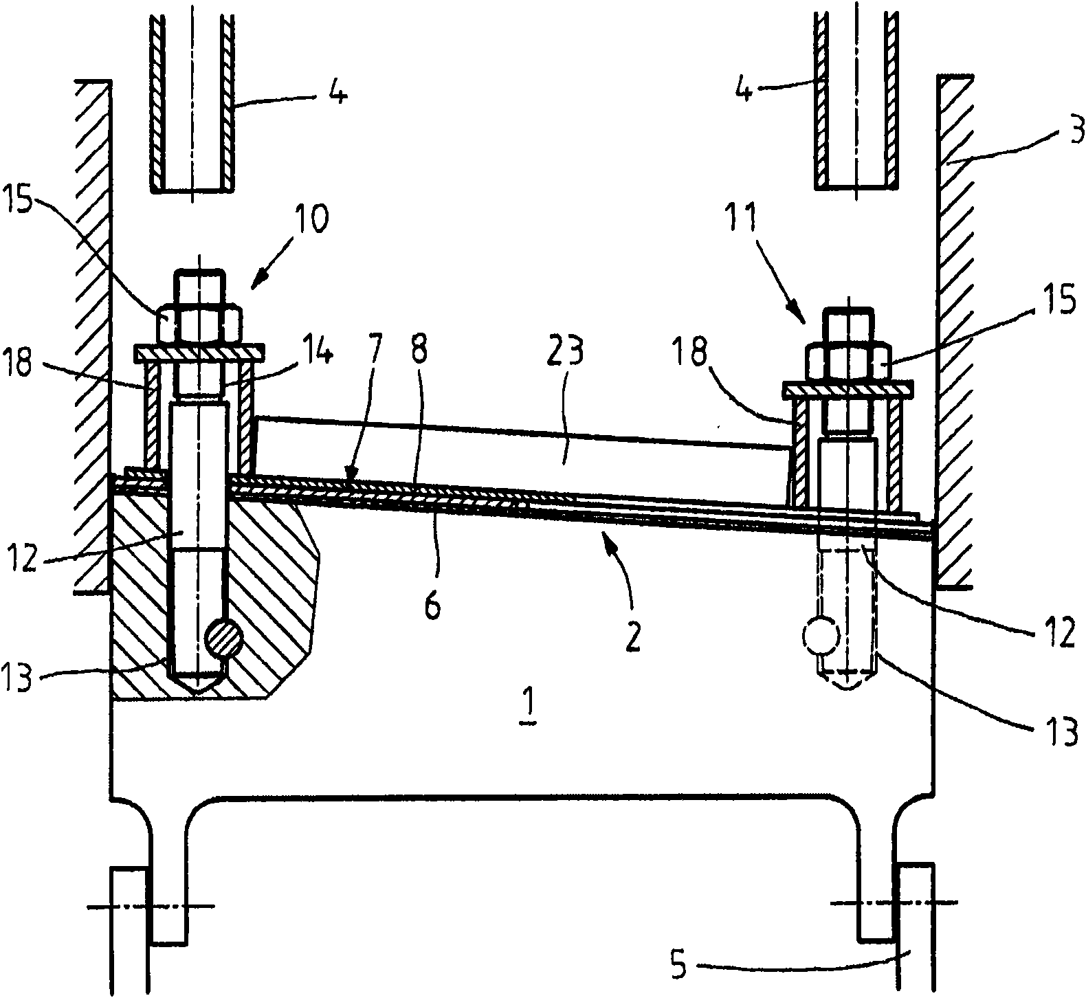
[0023] Figure 1 to Figure 8 The shown dummy bar head 1 is equipped with a dummy bar liner 2 according to the invention. The dummy bar liner 2 is shown in its starting position before the casting process begins, sealing the interior of the mold 3 for casting at the bottom of a steel pipe with a width of approximately 800 mm, a flange width of approximately 400 mm, and a web thickness of approximately 120 mm. Large double T-beam blanks. Above the dummy rod head 1 there is at least one pouring trough and channel 4 protruding into the mold through which molten steel is injected into the interior of the mold 3 during casting. Below the dummy bar head 1 , the dummy bar head 1 is connected to a withdrawal device 5 by means of which the bar is pulled out of the mold 3 .

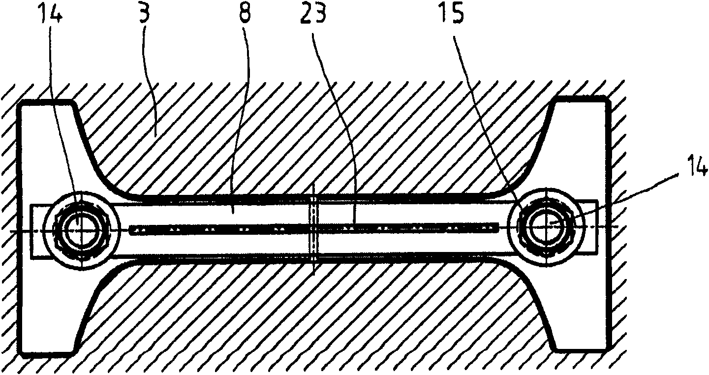
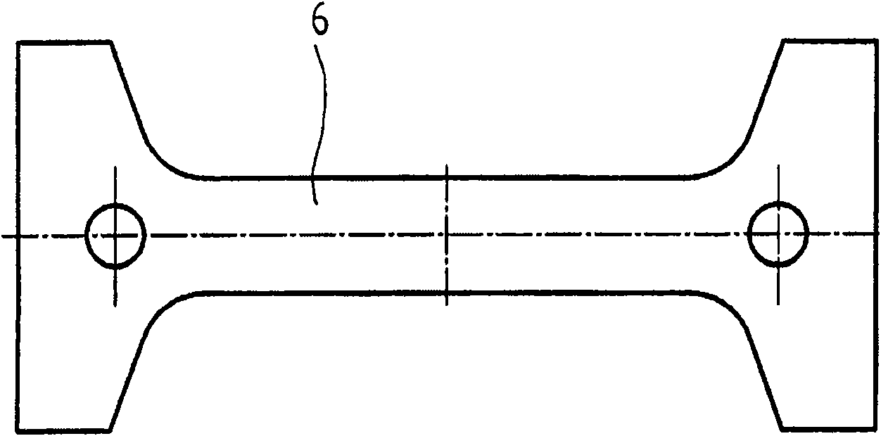
[0024] especially from figure 1 with figure 2 It can be seen that the dummy bar gasket 2 is composed of a flat gasket 6 and two lining plates 7 and 8, and the lining plate 7 is divided into two half plates 7a, ...


PUM

PropertyMeasurementUnit
lengthaaaaaaaaaa
thicknessaaaaaaaaaa

Abstract

In a system for sealing a dummy bar head in a mould of a continuous casting plant for casting large-format preliminary sections, a flat gasket ( 6) to seal the gap between the dummy bar head and the mould is provided, which is held on a packing plate (7) contained on the dummy bar head. Said packing plate has approximately the cross-sectional shape of the mould profile and covers the flat gasket (6). The packing plate (7) is displaceable towards the centre of the mould by an amount which is a function of the conicity of the mould (3). To this end, it consists of two plate halves (7a, 7b) lyingin one plane with respect to each other. This makes it possible, when inserting the dummy bar head, to compensate for the angled course of the mould with the contracting packing plate until the seali ng gap between packing plate and mould remains uniform on all sides.

Description

technical field [0001] The invention relates to a system for sealing the dummy rod head in a mold of a continuous casting plant for casting large preforms, the system having a flat gasket for sealing the gap between the dummy rod head and the mould, and a The flat spacer is fixed to a backing plate on the dummy bar head, which liner has a cross-sectional form substantially similar to or identical to the mold profile and completely covers the flat spacer. Background technique [0002] This type of continuous casting equipment is used, for example, to produce large so-called beam blank profiles, which are double T-shaped (or I-shaped), with a length of more than 800mm and a flange width of more than 400mm, and the web The thickness is about 120mm. Dummy pins are also used to seal the underlying mold before or during the casting start-up process, as is well known in the art. [0003] During casting, the melt is poured through pouring channels and channels into the cavity of t...

Claims


Application Information

Patent Timeline
Patent Type & Authority Applications(China)
IPC IPC(8): B22D11/08
CPCB22D11/083B22D11/088B22D11/08B22D11/20
Inventor T·迈耶
Owner CONCAST AG
Why Eureka
Try Eureka