
Mobile mining equipment

A kind of mining equipment and mobile technology, applied in the field of mobile mining equipment, can solve the problems of coal crushing, easy blockage, coal discharge inconvenience, etc., achieve the effect of smooth discharge process and prevent blockage of discharge port

Inactive Publication Date: 2020-07-17
JIANGSU VOCATIONAL INST OF ARCHITECTURAL TECH
View PDF12 Cites 5 Cited by
  • Summary
  • Abstract
  • Description
  • Claims
  • Application Information

AI Technical Summary

Problems solved by technology

[0003] In open-pit coal mining, mobile mining equipment is often used. However, the existing mobile mining equipment cannot crush coal while mining, and the coal discharge is inconvenient and easy to block

Method used


Image

  • Mobile mining equipment
  • Mobile mining equipment
  • Mobile mining equipment

Examples


Embodiment 1

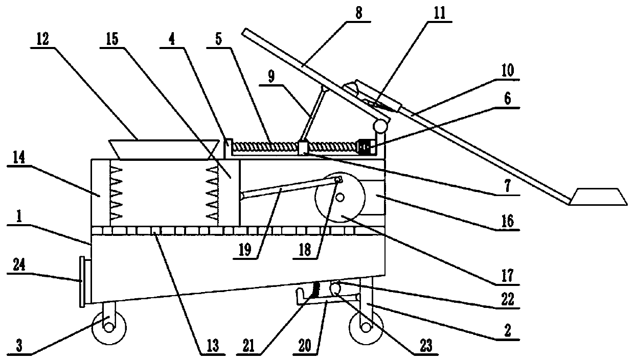
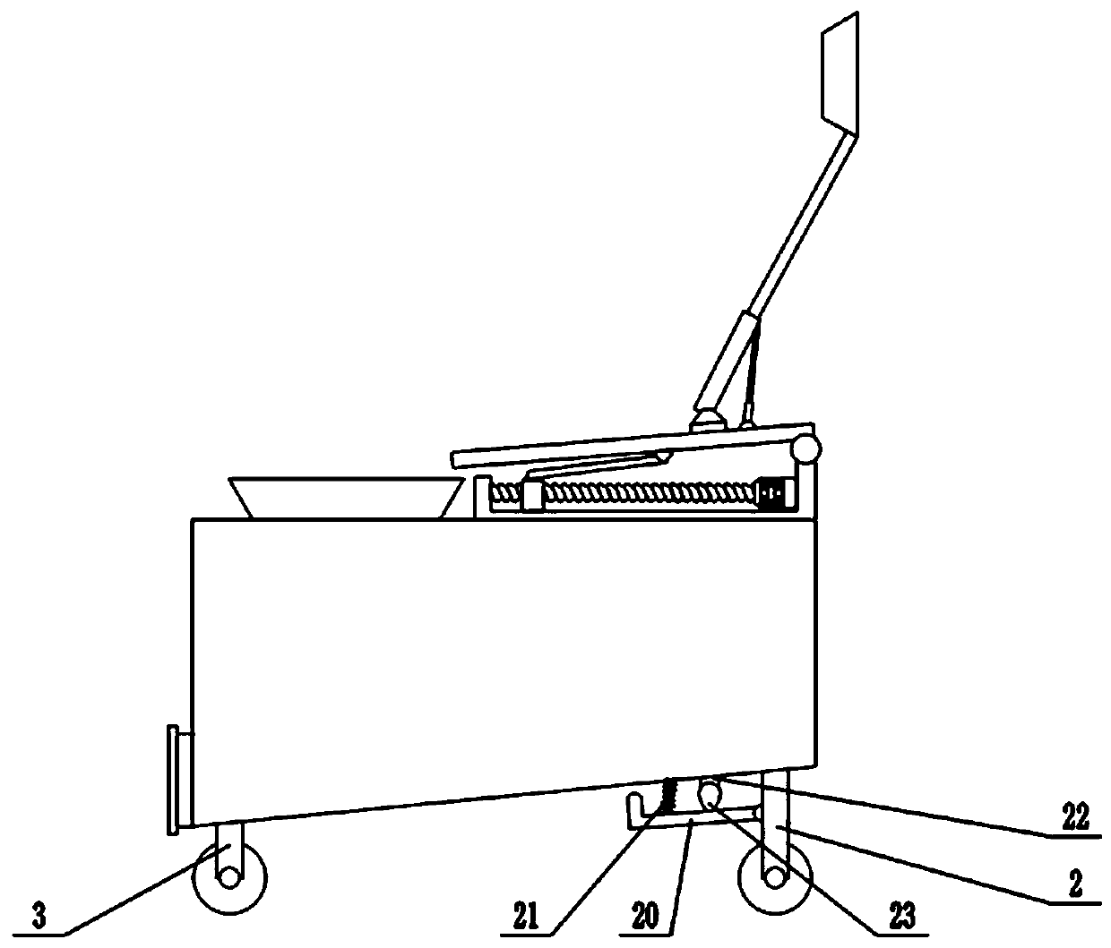
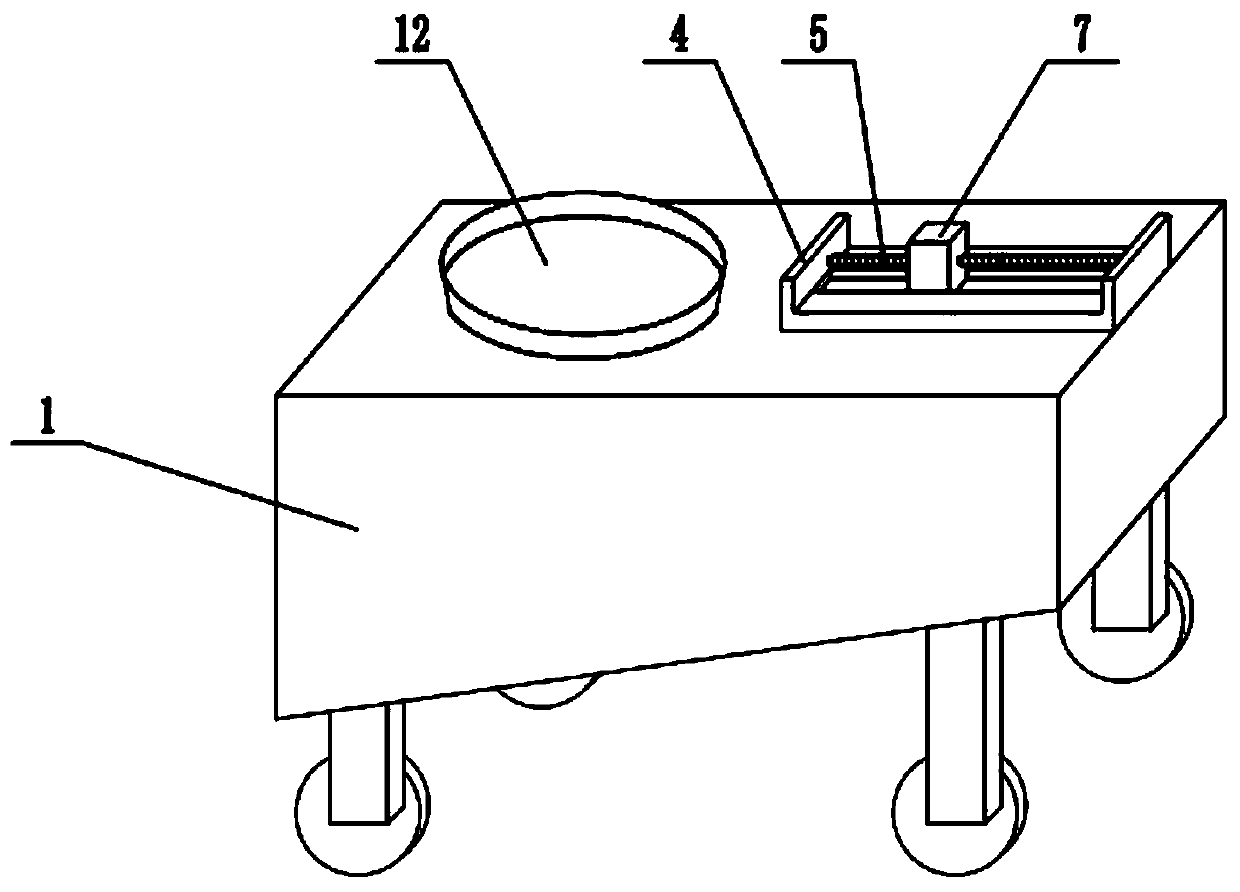
[0020] see Figure 1-3 , in the embodiment of the present invention, a kind of mobile mining equipment comprises housing 1, front wheel bracket 2, rear wheel bracket 3, movable plate 8 and bucket 10, and the bottom of housing 1 is installed with front wheel bracket 2, rear wheel bracket 3. The front wheel bracket 2 and the rear wheel bracket 3 are respectively equipped with rollers to facilitate the movement of the device. The upper surface of the housing 1 is fixedly connected with a fixed frame 4, and the inner wall of the fixed frame 4 is fixedly connected with a first motor 6. , the first motor 6 is a forward and reverse motor, the shaft extension end of the first motor 6 is equipped with a screw rod 5, the end of the screw rod 5 is rotatably connected with the side wall of the fixed frame 4, and a slider is set on the screw rod 5 7. The slider 7 is threadedly connected with the screw rod 5, and the lower surface of the slider 7 is slidably connected with the fixed frame 4...

Embodiment 2

[0022] On the basis of Embodiment 1, a percussion hammer 20 is provided below the housing 1, the end of the percussion hammer 20 is hinged with the front wheel bracket 2, and the middle part of the percussion hammer 20 is fixedly connected with an extension spring 21, and the end of the extension spring 21 The upper end is fixedly connected with the bottom of the casing 1, and under the action of the extension spring 21, the percussion hammer 20 can strike the bottom of the casing 1, and the lower surface of the casing 1 is fixedly connected with a third motor 22, and the shaft extension end of the third motor 22 A cam 23 is sleeved, and the cam 23 abuts against the middle part of the hammer 20, starts the third motor 22, drives the cam 23 to rotate, and when the protruding part of the cam 23 contacts with the hammer 20, drives the hammer 20 rotates downwards, and the cam 23 continues to rotate. Under the action of the tension spring 21, the hammer 20 is driven to rotate upward...


PUM


Abstract

The invention relates to the technical field of mining, in particular to mobile mining equipment. The mobile mining equipment comprises a shell, a front wheel support, a rear wheel support, a movableplate and a bucket, wherein the front wheel support and the rear wheel support are mounted at the bottom of the shell; the upper surface of the shell is fixedly connected with a fixing frame; the movable plate is hinged to the right end of the fixing frame; a first connecting rod is hinged to the upper surface of a sliding block, the top end of the first connecting rod is hinged to the lower surface of the movable plate, the upper surface of the movable plate is hinged with the bucket, a sieve plate is arranged inside the shell, the left inner wall of the left side of the shell is fixedly connected with a left crushing plate, the upper surface of the sieve plate is slidably connected with a right crushing plate, the left crushing plate and the right crushing plate are used for crushing coal, the crushed coal passes through the sieve plate and falls to the bottom of the shell, the bottom of the shell is inclined, the crushed coal can be discharged through a discharge port, the bottom ofthe shell is knocked by a knocking hammer, and the bottom of the shell is vibrated, so that the coal is discharged from the discharge port, and the discharge process is smoother.

Description

technical field [0001] The invention relates to the technical field of mining, more specifically, a mobile mining equipment. Background technique [0002] It is an area where humans mine coal resources in coal-rich mining areas, generally divided into underground coal mines and open-pit coal mines. When the coal seam is far away from the surface, it is generally selected to excavate the coal by digging the roadway underground, which is an underground coal mine. When the distance between the coal seam and the surface is very short, it is generally chosen to directly strip the surface soil layer to excavate coal, which is an open-pit coal mine. [0003] In open-pit coal mining, mobile mining equipment is often used. However, the existing mobile mining equipment cannot crush coal while mining, and the coal discharge is inconvenient and easy to block. Contents of the invention [0004] The object of the present invention is to provide a mobile mining equipment to solve the p...

Claims


Application Information

Patent Timeline
Patent Type & Authority Applications(China)
IPC IPC(8): B02C1/00B02C23/16B02C23/02B65D88/66E21C35/20
CPCB02C1/00B02C23/02B02C23/16B02C2023/165B65D88/66E21C35/20
Inventor 郭玉程强强王玮张领雷肖藏岩
Owner JIANGSU VOCATIONAL INST OF ARCHITECTURAL TECH
Learn More