Trailer structure for road management

A technology of road management and trailer, which is applied in the field of trailer structure for road management, which can solve the problems of safety hazards for vehicle personnel, large space occupied by trailers, hidden safety hazards, etc. The effect of space occupation

Active Publication Date: 2022-06-24
HUBEI PERFECT ENG MACHINERY
View PDF0 Cites 0 Cited by
  • Summary
  • Abstract
  • Description
  • Claims
  • Application Information

AI Technical Summary

Problems solved by technology

[0002] With the continuous development of the modern automobile industry, more and more cars are used in people's lives, and traffic jams even appear in many cities. Although cars can provide great convenience for our production and life, but after the failure of the vehicle It is still very troublesome. When the vehicle is forced to stop due to a breakdown on the road, the vehicle personnel are not only in danger of safety, but also hinder the normal traffic on the road. Therefore, it is necessary to use a trailer to move the vehicle. The trailer can not only It is suitable for dealing with common emergencies, and it can also carry out mobile measures for illegally parked vehicles
[0003] Although the existing trailers can meet the basic needs of use, the disadvantages are still very obvious. The main manifestations are: the situation of the vehicle malfunction is uncertain, so many car owners need to place the trailer in the car, but currently The trailer takes up a lot of space, which is not conducive to the rational use of the space in the car; the height of the existing trailer for the vehicle is mostly fixed. When the vehicle fails on the uneven road surface, the stones on the road, etc. Foreign objects often scratch the bottom of the trailer, which affects the movement of the vehicle; the current trailer lacks a brake structure, and when the vehicle fails on a road with a slope, it may be difficult to use the trailer to control the direction of the vehicle's movement , and even cause safety hazards

Method used


Image

  • Trailer structure for road management
  • Trailer structure for road management
  • Trailer structure for road management

Examples


Embodiment Construction

[0021] The technical solutions in the embodiments of the present invention will be clearly and completely described below with reference to the accompanying drawings in the embodiments of the present invention. Obviously, the described embodiments are only a part of the embodiments of the present invention, but not all of the embodiments. Based on the embodiments of the present invention, all other embodiments obtained by those of ordinary skill in the art without creative efforts shall fall within the protection scope of the present invention.

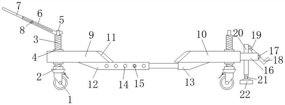
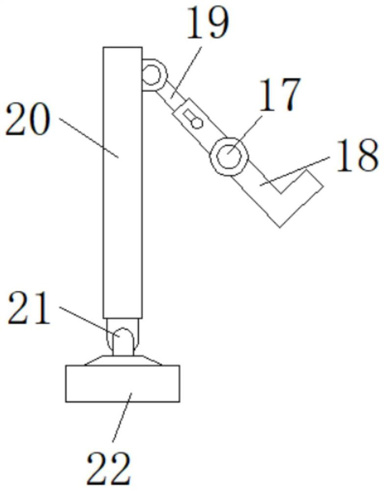
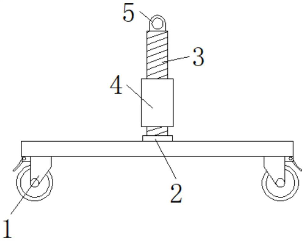
[0022] see Figure 1-4 , a road management trailer structure, including a universal wheel 1, the top surface of the universal wheel 1 is fixedly connected with a bearing one 2, the middle part of the bearing one 2 is fixedly sleeved on the bottom end of the threaded rod 3, the threaded rod 3 The lower thread is sleeved in the middle of the threaded ring 4, the top of the threaded rod 3 is fixedly connected with a fixed ring 5, the mid...


PUM


Abstract

The invention relates to the technical field of trailers, and discloses a trailer structure for road management, which includes a universal wheel, the top surface of the universal wheel is fixedly connected with a bearing 1, and the middle part of the bearing 1 is fixedly sleeved on the screw thread. The bottom end of the rod, the lower part of the threaded rod is threaded in the middle of the spiral ring, the top of the threaded rod is fixedly connected with a fixed ring, and the middle part of the fixed ring is movably socketed with a pry bar protruding from the outer body . The present invention adopts the design of the prying tube and the transmission rod. When it is necessary to tow the vehicle on the slope, the prying bar can be sleeved in the inner cavity of the prying tube. If the vehicle on the trailer is out of control on the slope , you can pull the pry bar upwards in time, then the rubber sheet will be closely attached to the ground, thereby increasing the friction between the trailer and the ground until the vehicle is stopped, which solves the problem that the transmission trailer lacks a braking structure , reflecting the safety of the device.

Description

technical field [0001] The invention relates to the technical field of trailers, in particular to a trailer structure for road management. Background technique [0002] With the continuous development of the modern automobile industry, there are more and more cars in people's lives, and many cities have even experienced traffic jams. Although cars can provide great convenience to our production and life, after the vehicles are out of order It is still very troublesome. When the vehicle is forced to stop due to a fault on the road, the vehicle personnel will not only be in danger of safety, but also hinder the normal traffic of the road. Therefore, it is necessary to use the trailer to move the vehicle. The trailer can not only It is suitable for the processing of ordinary emergencies, and can also carry out mobile measures for illegally parked vehicles. [0003] Although the existing trailers can meet the basic needs of use, the drawbacks are still very obvious. The main ma...

Claims


Application Information

Patent Timeline
Patent Type & Authority Patents(China)
IPC IPC(8): B60S13/02
CPCB60S13/02
Inventor 胡夏妹黄亚飞
Owner HUBEI PERFECT ENG MACHINERY
Why Eureka
Try Eureka