Construction technology of a connection structure between corrugated arched steel plates and steel beams

A construction technology and connection structure technology, applied in bridges, bridge materials, bridge construction, etc., can solve problems such as inconvenient operation, difficult welding, and change in section size, and achieve simple construction, easy quality assurance, and improved lateral bending resistance The effect of stiffness

Active Publication Date: 2021-08-10
JIANGXI PROVINCIAL EXPRESSWAY INVESTMENT GRP CO LTD
View PDF9 Cites 0 Cited by
  • Summary
  • Abstract
  • Description
  • Claims
  • Application Information

AI Technical Summary

Problems solved by technology

The problem of the connection between the corrugated arched steel plate and the steel beam is more prominent: firstly, the end profile of the corrugated steel plate is a sinusoidal curve or a multi-segment continuous circular curve, which is extremely inconvenient to operate when it is blocked with a flat steel plate, and continuous welding is used. When connecting the corrugated steel plate and the flat steel plate, the welding is difficult due to the thinness of the plate and the continuous curve change; and when the arched form with variable cross-section is used, the steel arch is supported by the upper flange of the steel beam during the pouring of concrete Slippage occurs in the transverse bridge direction, resulting in changes in the cross-sectional dimensions of the arched composite bridge deck

Method used


Image

  • Construction technology of a connection structure between corrugated arched steel plates and steel beams
  • Construction technology of a connection structure between corrugated arched steel plates and steel beams
  • Construction technology of a connection structure between corrugated arched steel plates and steel beams

Examples


Embodiment Construction

[0029] The following will clearly and completely describe the technical solutions in the embodiments of the present invention with reference to the accompanying drawings in the embodiments of the present invention. Obviously, the described embodiments are only some, not all, embodiments of the present invention. Based on the embodiments of the present invention, all other embodiments obtained by persons of ordinary skill in the art without making creative efforts belong to the protection scope of the present invention.

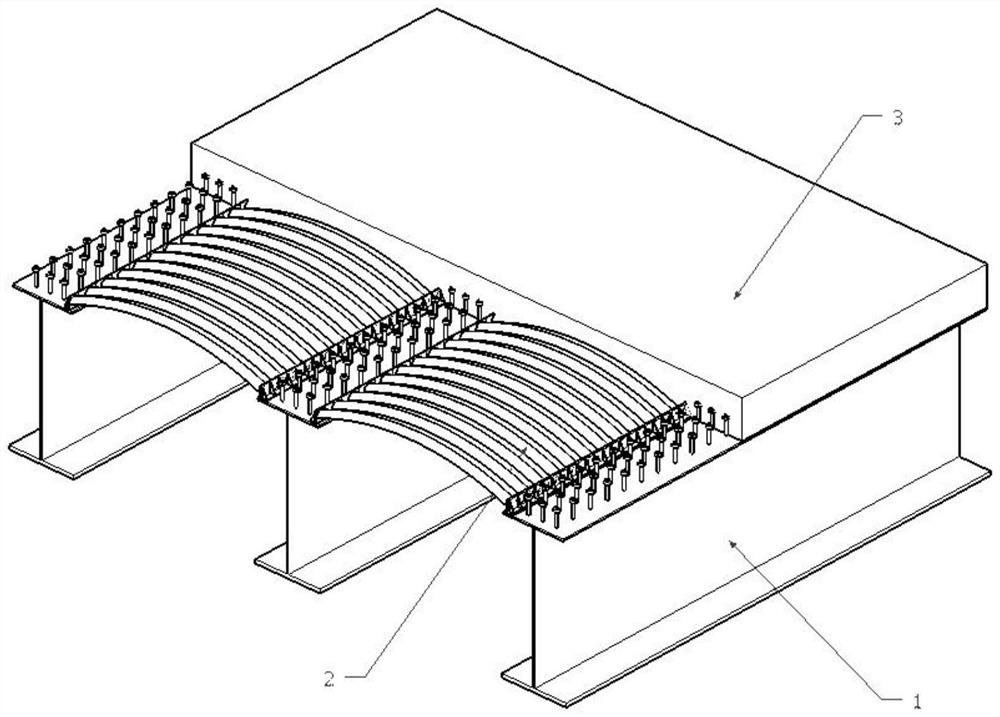
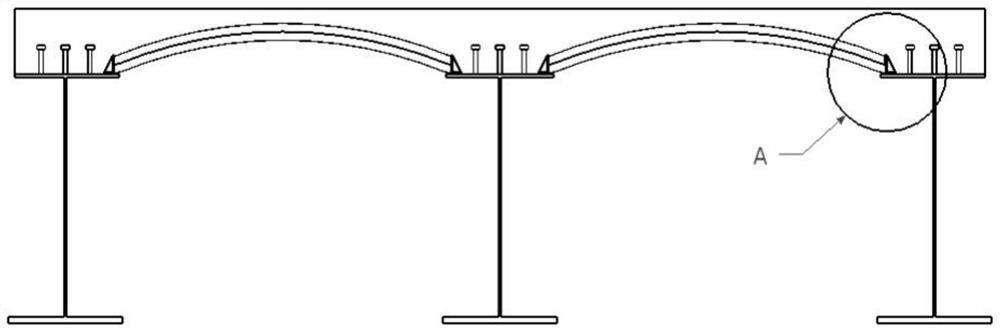
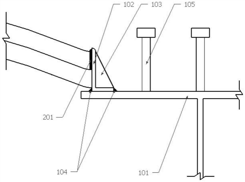
[0030] The object of the present invention is to provide a construction technique for the connection structure between corrugated arched steel plates and steel beams, which is used to prevent grout leakage at the ends of corrugated arched steel plates and cross-bridge slippage during pouring of concrete.

[0031] In order to make the above objects, features and advantages of the present invention more comprehensible, the present invention will be further descri...


PUM


Abstract

The invention discloses a construction process of a connection structure between a corrugated arched steel plate and a steel beam, comprising the following steps: welding a triangular steel plate with the same inner contour size as the angle steel to the angle steel to form a component with a plurality of transverse stiffeners ; Weld the studs and the member to the upper flange of the steel beam; make the corrugated arched steel plate span across two adjacent steel beams, and the two ends of each corrugated arched steel plate are connected to the upper flange of the steel beam Maintain horizontal contact and maintain vertical contact with the vertical limb of the angle steel; paste rubber sealing strips on the upper surface of the corrugated arched steel plate at the gap in contact with the angle steel; Reinforcement is placed and tied according to size, and then concrete is poured. Compared with the prior art, the invention can prevent grout leakage at the end of the corrugated arched steel plate and slippage in the transverse bridge direction during concrete pouring, and has simple construction, easy quality assurance and fast construction speed.

Description

technical field [0001] The invention relates to the technical field of bridge construction, in particular to a construction process for a connection structure between a corrugated arched steel plate and a steel beam. Background technique [0002] Composite bridge decks are generally composed of steel plates and concrete, among which steel plates are mostly flat steel plates, and stiffeners are welded on them, relying on the stiffeners to provide the necessary rigidity to meet the rigidity requirements of concrete construction. When connecting with the steel beam, usually the flat steel plate is directly welded on the upper flange of the steel beam first, so that the flat steel plate and the upper flange are airtightly connected as a whole, so as to ensure that no grout leakage occurs when pouring concrete. [0003] In engineering, corrugated profiled steel plates and concrete are also used to form composite bridge decks. During construction, the profiled steel plate is plac...

Claims


Application Information

Patent Timeline
Patent Type & Authority Patents(China)
IPC IPC(8): E01D21/00E01D19/12E01D101/30
CPCE01D19/125E01D21/00E01D2101/30
Inventor 俞文生曾明辉徐义标吴文清冯小毛
Owner JIANGXI PROVINCIAL EXPRESSWAY INVESTMENT GRP CO LTD
Why Eureka
Try Eureka