Layered suspension structure of single-side double-main-cable steel truss stiffening girder suspension bridge

A suspension structure and steel truss technology, applied in suspension bridges, erecting/assembling bridges, bridges, etc., can solve the problems of increasing the dead load of stiffening beams, concentrating the force at the lifting point, occupying the bridge deck, etc., reducing the width of the bridge deck and reducing the constant load. load and reduce the effect of S-shaped deflection

Inactive Publication Date: 2020-07-17
SOUTHWEST JIAOTONG UNIV
View PDF5 Cites 3 Cited by
  • Summary
  • Abstract
  • Description
  • Claims
  • Application Information

AI Technical Summary

Problems solved by technology

However, the suspension structure system has the following two problems: ①Since the double main cables are connected to the upper bridge deck of the stiffened beam, the suspension area of ​​the main cable occupies the width of the bridge deck, thus increasing the dead load of the stiffened beam 1. The force of the sling is large and the force of the lifting point is too concentrated; ②Since the length of the slings of the double main cables is the same, it is easy to cause the resonance of the same frequency of the slings or the cable vibration caused by the wake

Method used


Image

  • Layered suspension structure of single-side double-main-cable steel truss stiffening girder suspension bridge
  • Layered suspension structure of single-side double-main-cable steel truss stiffening girder suspension bridge
  • Layered suspension structure of single-side double-main-cable steel truss stiffening girder suspension bridge

Examples


Embodiment Construction

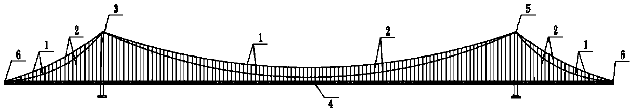
[0019] Such as Figure 1-5 As shown, a single-sided double main cable steel truss stiffened girder suspension bridge layered suspension structure system, single-sided double main cable 1 adopts the unequal height arrangement of "one main cable on the top and one main cable on the bottom" , or adopt the parallel layout of the inner and outer main cables, or adopt the double-chain arrangement of the inner and outer main cables. Among them, there are two main cables 1 on one side of the transverse bridge (four on both sides). The main cable 1 is connected with the corbel protruding from the lower chord of the steel truss stiffening beam 4 through the cable clamp and the sling 2.

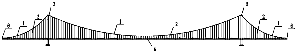
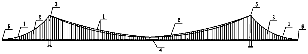
[0020] Such as Figure 6 , as shown in 7, the current commonly used single-side single main cable suspension bridge structure system and the existing single-side double main cable suspension bridge structure system, the main cable 1 and the steel truss stiffening beam 4 are connected in the same way: ...


PUM


Abstract

The invention discloses a layered suspension structure of a single-side double-main-cable steel truss stiffening girder suspension bridge. A main cable close to the inner side of a bridge deck is connected to an upper chord of a steel truss stiffening girder through a cable clamp and a sling, and a main cable close to the outer side of the bridge deck is connected to a bracket extending out of a lower chord of the steel truss stiffening girder through a cable clamp and a sling. The single-side double main cables are arranged at different heights with one cable arranged at the upper part, and the other main cable arranged at the lower part, or the inner side main cable and the outer side main cable are arranged in parallel at the same height, or the inner side main cable and the outer sidemain cable are arranged in a double-chain manner. The bridge deck width occupied by the main cable suspension area can be reduced, so that the dead load of the stiffening girder is reduced, and the transverse width of the bridge tower is also reduced. The problem that the lifting point force is excessively concentrated on the upper (or lower) layer node can be effectively reduced by layered suspension. The inner and outer slings are different in length, so that same-frequency resonance of the slings can be avoided. The heights of the inner and outer main cables are different, so that cable vibration caused by wake flow can be avoided. If the double main cables are arranged in a double-chain form, the S-shaped deflection of the stiffening girder can be reduced.

Description

technical field [0001] The invention relates to the technical field of suspension bridge structures, in particular to a layered suspension structure of a steel truss stiffened beam suspension bridge with double main cables on one side. Background technique [0002] The suspension bridge has beautiful shape and strong spanning ability, and is one of the preferred structural forms of long-span bridges. At present, there are 26 suspension bridges with a span of more than 1000m that have been built or are being built in China (including highway and railway bridges). Among them, the span of Wuhan Yangsigang Bridge reaches 1700m, which is the largest suspension bridge in China. The suspension bridge with the largest span in the world is the Akashi Kaikyo Bridge in Japan, with a span of 1991m. With the increasingly mature technology of design and construction of long-span suspension bridges, coupled with the urgent engineering demand for super-long-span bridge structures of cross-...

Claims


Application Information

Patent Timeline
Patent Type & Authority Applications(China)
IPC IPC(8): E01D21/00E01D19/12E01D11/02
CPCE01D11/02E01D19/125E01D21/00
Inventor 沈锐利陈巍闫勇苗如松薛松领
Owner SOUTHWEST JIAOTONG UNIV
Why Eureka
Try Eureka