Column and beam connecting device

A connecting device and column-beam technology, which is applied in the direction of architecture and building construction, can solve the problems of weak connection reliability and connection strength, and achieve the effect of improving reliability and stability

Pending Publication Date: 2020-07-17
YANGZHOU POLYTECHNIC INST
View PDF0 Cites 2 Cited by
  • Summary
  • Abstract
  • Description
  • Claims
  • Application Information

AI Technical Summary

Problems solved by technology

[0004] However, in the above-mentioned connection method, the stress point falls on the pin, which leads to relatively weak connection reliability, making the connection strength between the beam and the column weak

Method used


Image

  • Column and beam connecting device
  • Column and beam connecting device
  • Column and beam connecting device

Examples


Embodiment 1

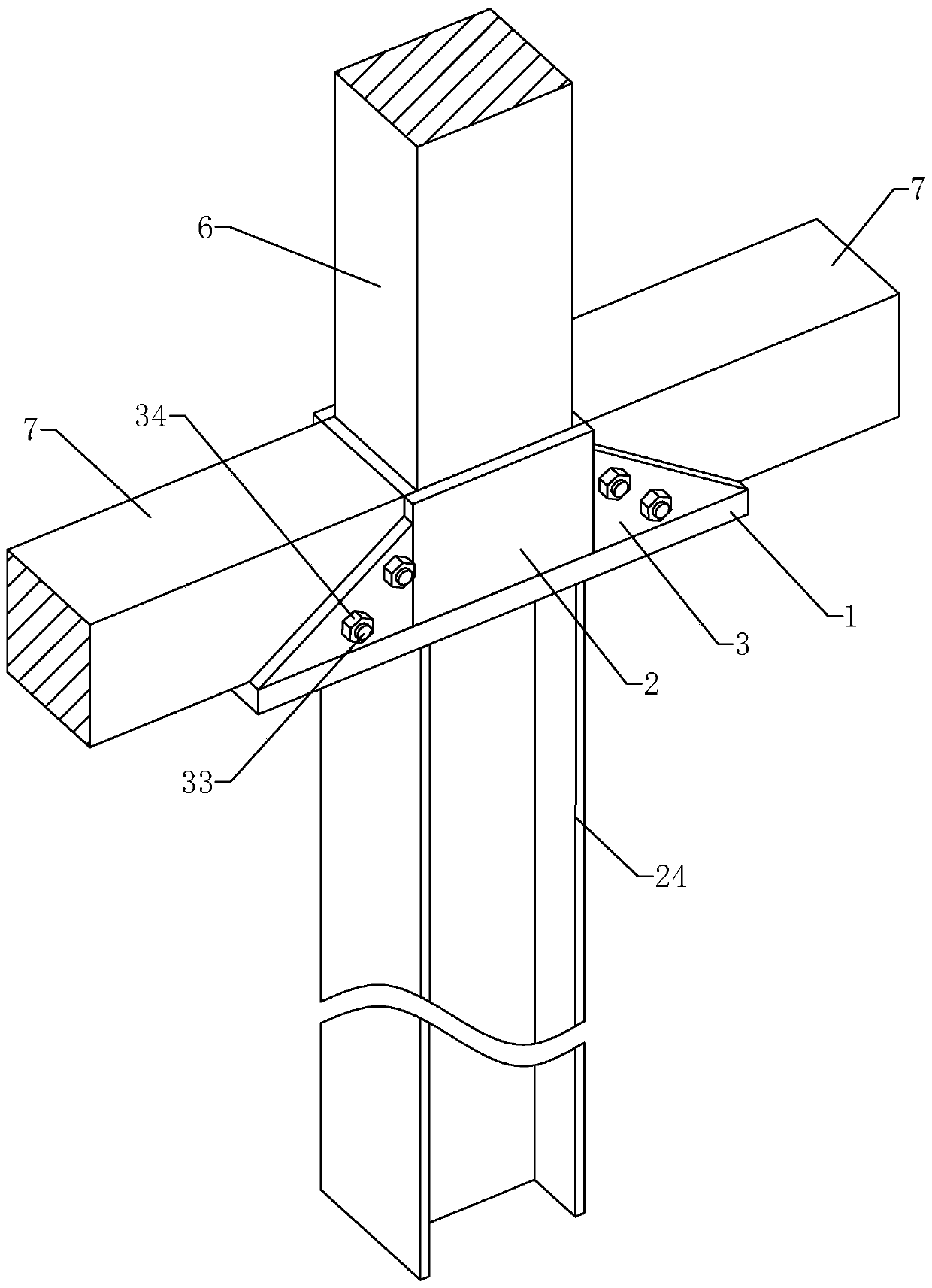
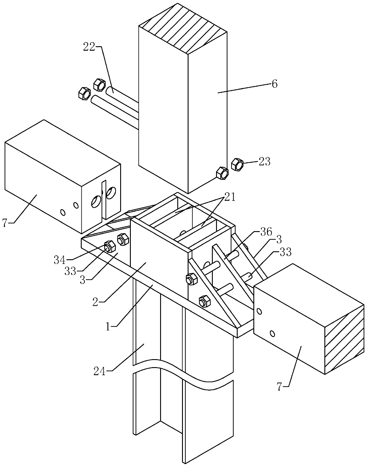
[0035] Example 1: Reference figure 1 and figure 2 , a column-beam connecting device, comprising a steel base plate 1, a steel hoarding plate 2 fixed on the steel base plate 1 by welding and used for fixing a column 6, and a splint 3 fixed on the steel base plate 1 by welding for fixing a beam 7 , the steel hoarding 2 can be a square frame, a round frame or other shapes, the steel hoarding 2 has the same cross-sectional shape as the column 6, the column 6 is located inside the steel hoarding 2, and the beam 7 is located outside the steel hoarding 2; One or more crossbeams 7 can be arranged on the steel bottom plate 1, one crossbeam 7 corresponds to two splints 3, and the two splints 3 clamp the crossbeam 7 in the middle. A first screw 22 is pierced on the steel hoarding 2 along a direction perpendicular to the column 6, the first screw 22 runs through the column 6 and the steel hoarding 2, and a first lock cap 23 is threaded at both ends of the first screw 22 , so that the c...

Embodiment 2

[0037] Example 2: Reference figure 1 and figure 2 , a column-beam connecting device, on the basis of Embodiment 1, also includes a steel inserting plate 21 arranged on the inner side of the steel enclosure 2, the steel inserting plate 21 is fixed on the steel bottom plate 1, and the fixing method can be welded or riveted . A slot is provided on the column 6, and the steel plate 21 is plugged on the column 6 through the slot, and the first screw 22 is inserted on the steel plate 21 and the column 6 at the same time. A positioning block 36 is fixedly arranged on the steel base plate 1 by welding, and the positioning block 36 is located between the two splints 3 and corresponds to the beam 7 one by one. The second screw rod 33 passes through the positioning block 36 at the same time, and the positioning block 36 is inserted into the On the beam 7 , the positioning block 36 further restricts the lateral displacement of the beam 7 , and the second screw 33 passes through the pos...

Embodiment 3

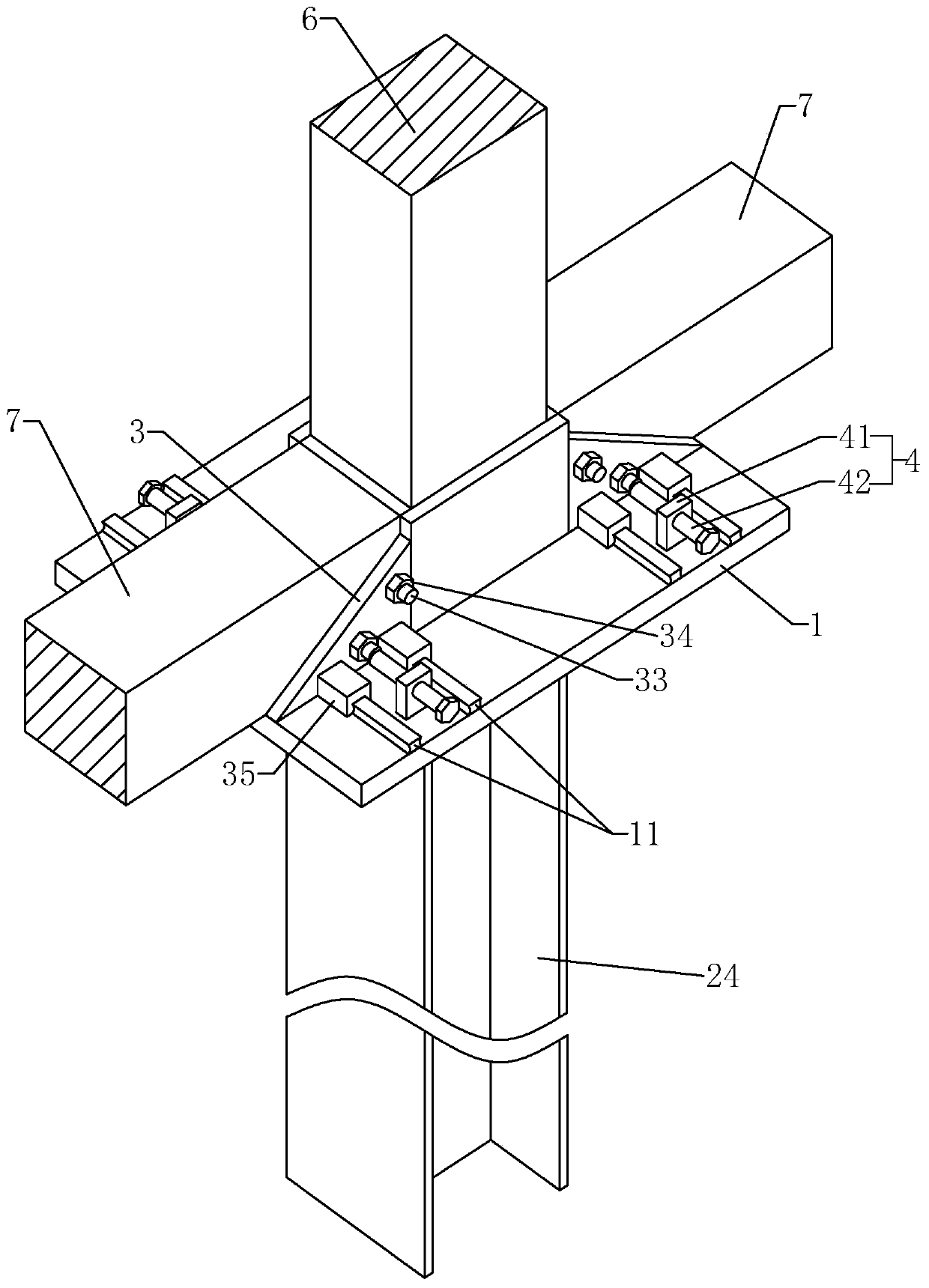
[0038] Example 3: Reference image 3 , a column-beam connection device, the difference from Embodiment 1 and Embodiment 2 is that the connection mode between the splint 3 and the steel floor 1 is different. The limit rail 11 is welded on the steel base plate 1 in a direction perpendicular to the crossbeam 7, and the splint 3 is welded with a sliding sleeve 35 that slides and is connected to the limit rail 11. The limit rail 11 limits the splint 3 to only extend the limit rail. The longitudinal direction of 11 slides, and can not disengage from limit rail 11. Such setting is convenient for on-site installation, so that the splint 3 can clamp the beams 7 of different sizes.

[0039] refer to image 3 , The limit component 4 is also set on the steel bottom plate 1, and the limit component 4 is used to fix the position of the splint 3 after sliding. The limit assembly 4 includes a limit block 41 fixed on the steel base plate 1, a limit rod 42 threaded on the limit block 41 alon...


PUM


Abstract

The invention relates to a column and beam connecting device applied to the technical field of buildings. The technical problem that columns and beans are not firmly connected is solved. The column and beam connecting device comprises a steel bottom plate, a steel coaming fixed to the steel bottom plate and used for limiting a vertical column and a clamping plate fixed to the steel bottom plate and used for limiting a cross beam. A first screw for locking the vertical column on the steel coaming is arranged on the steel coaming in a penetrating manner, and the two ends of the first screw protrude out of the steel coaming and then are in threaded connection with first locknuts. A second screw for locking the cross beam to the clamping plate is arranged on the clamping plate in a penetratingmanner, and the two ends of the second screw protrude out of the clamping plate and then are in threaded connection with second locknuts. The column and beam connecting device has the effect of improving the firmness and the stability of the connection of the cross beam and the vertical column.

Description

technical field [0001] The invention relates to the technical field of construction, more specifically, it relates to a column-beam connecting device. Background technique [0002] According to the experimental research and the analysis of engineering examples, it is found that the damage of column and beam structures mostly occurs at the connection joints of columns and beams, and the main reason for the failure is caused by the lack of bearing capacity, stiffness or ductility of the joints. Splicing has always been one of the focuses of research in architecture. [0003] In the field of wood structure construction, steel structure connectors are required to allow beams to be installed on columns. Most of the existing connectors are L-shaped steel plates, the two sides of the steel plate are in contact with the column and the beam respectively, and then the pins are inserted on the steel plate, and the pins are simultaneously inserted on the steel plate and the column or o...

Claims


Application Information

Patent Timeline
Patent Type & Authority Applications(China)
IPC IPC(8): E04B1/58E04B1/26
CPCE04B1/2604E04B2001/2676
Inventor 沈杰张苏俊朱旭东黄玲玲
Owner YANGZHOU POLYTECHNIC INST
Why Eureka
Try Eureka