Single fast reactor component thermal bending test restraint device and thermal deformation contact measurement method

A technology of restraint device and thermal bending, which is used in reactors, nuclear reactor monitoring, and greenhouse gas reduction, etc., can solve the problems of thermal deformation of fast reactor components, and the inability to measure the three-dimensional displacement and contact force of fast reactor components.

Active Publication Date: 2019-04-16
XI AN JIAOTONG UNIV
View PDF9 Cites 1 Cited by
  • Summary
  • Abstract
  • Description
  • Claims
  • Application Information

AI Technical Summary

Problems solved by technology

[0005] In order to overcome the above-mentioned problems in the prior art, the object of the present invention is to provide a thermal bending test restraint device for a single fast reactor component and a thermal deformation contact measurement method, which can restrain the upper block and the lower block of the fast reactor component The lateral displacement in six directions solves the problem that the fast reactor components cannot be thermally deformed in different directions in the prior art; the measurement method of the present invention can measure the temperature distribution of the fast reactor components, the three-dimensional displacement after thermal deformation, and the contact at the pad Force, to solve the problem that in the prior art, it is impossible to measure the three-dimensional displacement of fast reactor components and the magnitude of contact force in different directions

Method used


Image

  • Single fast reactor component thermal bending test restraint device and thermal deformation contact measurement method
  • Single fast reactor component thermal bending test restraint device and thermal deformation contact measurement method
  • Single fast reactor component thermal bending test restraint device and thermal deformation contact measurement method

Examples


Embodiment Construction

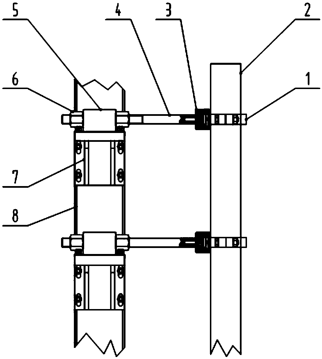
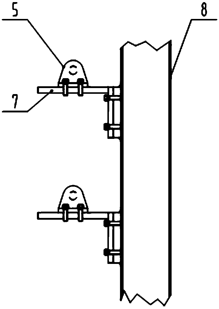
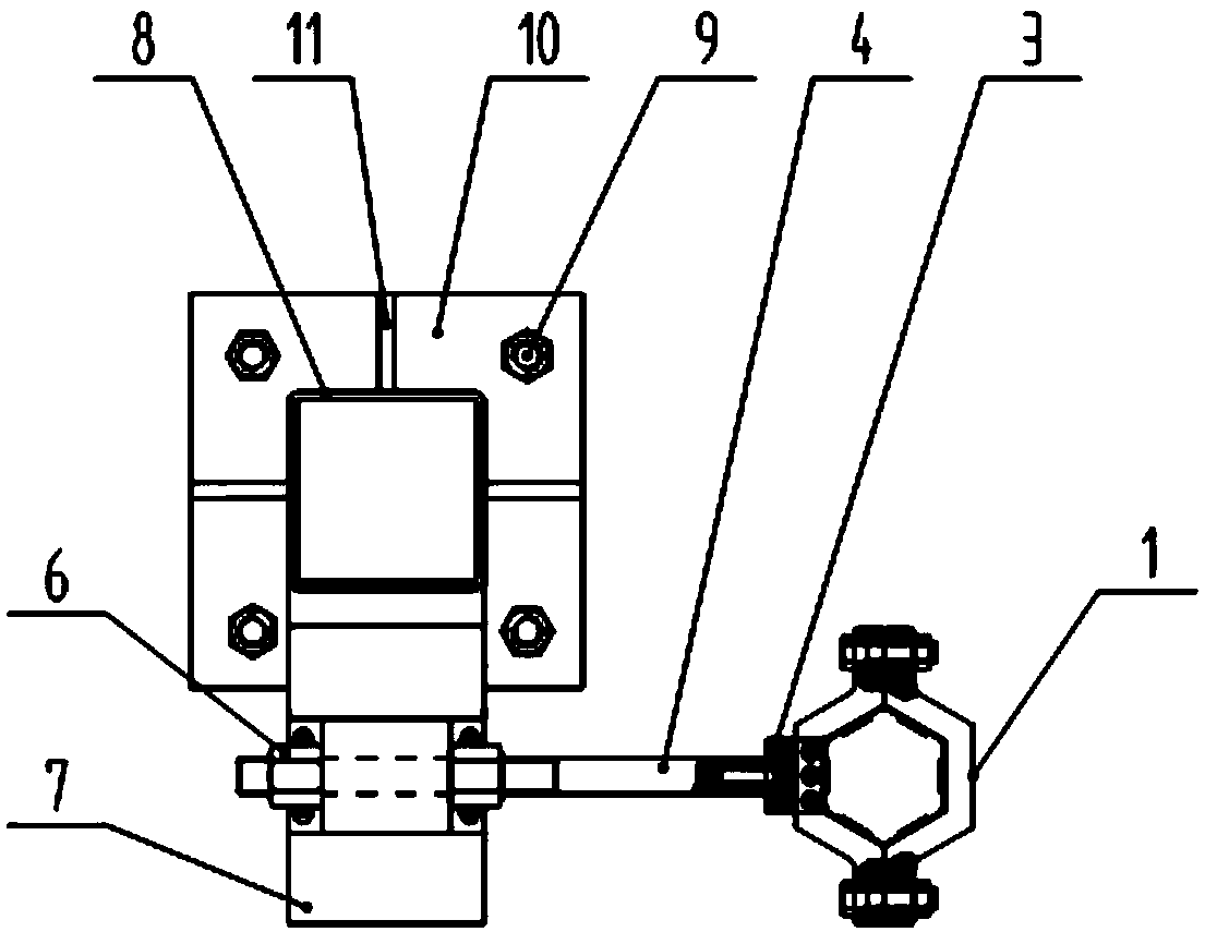
[0030] The implementation of the present invention will be illustrated by specific specific examples below, and those skilled in the art can easily understand other advantages and effects of the present invention from the contents disclosed in this specification.

[0031] The structures, proportions, sizes, etc. shown in the drawings of this specification are only used to cooperate with the content disclosed in the specification for the understanding and reading of those who are familiar with this technology, and are not used to limit the conditions for the implementation of the present invention. Any The modification of the structure, the modification of the proportional relationship or the adjustment of the size should still fall within the scope covered by the technical content explained in the present invention without affecting the effects and goals that the present invention can produce. Terms such as "upper", "middle", "lower", "left", "right", etc. quoted in this specif...


PUM


Abstract

The present invention discloses a single fast reactor assembly thermal bending test restraining apparatus and a thermal deformation contact measurement method thereof. The apparatus comprises a vertical column, wherein the upper portion and the middle portion of the vertical column are respectively provided with a supporting seat, each supporting seat is provided with a screw rod fixation seat, a screw rod can linearly move on the screw rod fixation seat, both sides of the screw rod fixation seat are respectively provided with a screw cap for fixing the screw rod, and the screw rod and a hexagonal hoop are connected through a C-shaped connection member. The invention further provides a method for performing thermal deformation contact measurement by using the apparatus. According to the present invention, with the single fast reactor assembly thermal bending test restraining apparatus, the restraining and the force applied on the single fast reactor assembly in the actual reactor are simulated to the maximum extent; and the thermal deformation contact measurement method provides the rich and effective data for the research of the thermal-deformation-contact mechanism of the single fast reactor assembly.

Description

technical field [0001] The invention belongs to the technical field of thermal bending tests of fast reactor components, and in particular relates to a constraining device for thermal bending tests of a single fast reactor component and a thermal deformation contact measurement method. Background technique [0002] After the sodium-cooled fast reactor is loaded, the core casing constrains the peripheral components, and the internal components are restrained by the mutual contact between the upper and lower pads of the hexagonal casing. After the reactor is in operation, high temperature, high pressure difference, and high neutron flux can cause components to bend and deform, and the contact force between adjacent components will cause more serious bending. Large component deformation will adversely affect the safe operation of nuclear power plants. Such as increasing the insertion and withdrawal force of components, difficulty in switching components, accelerating component ...

Claims


Application Information

Patent Timeline
Patent Type & Authority Patents(China)
IPC IPC(8): G21C17/08
CPCG21C17/08Y02E30/30
Inventor 巫英伟苏光辉马泽华秋穗正田文喜马振辉
Owner XI AN JIAOTONG UNIV
Why Eureka
Try Eureka