A multifunctional compact center pin traction device

A traction device, a compact technology, applied in the direction of the traction device, the device for lateral relative movement between the chassis and the bogie, transportation and packaging, etc., can solve the problem of large welding volume of the traction seat, easy interference, and center pin seat functions Single and other problems, to achieve the effect of simple structure, complete functions, and high installation point

Active Publication Date: 2017-03-22
ZHUZHOU ELECTRIC LOCOMOTIVE CO LTD
View PDF1 Cites 1 Cited by
  • Summary
  • Abstract
  • Description
  • Claims
  • Application Information

AI Technical Summary

Problems solved by technology

This device largely solves the problem of large welding amount of traction seat, single function of center pin seat, and easy interference

Method used


Image

  • A multifunctional compact center pin traction device
  • A multifunctional compact center pin traction device
  • A multifunctional compact center pin traction device

Examples


Embodiment Construction

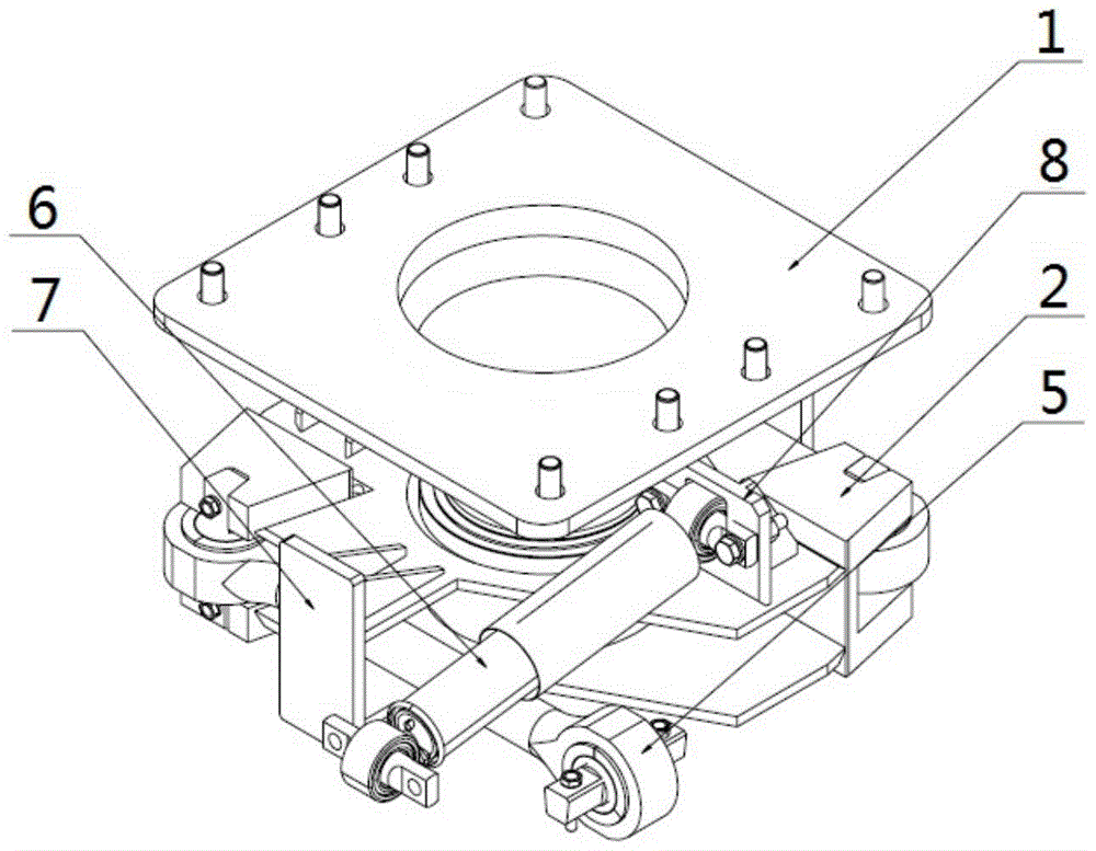
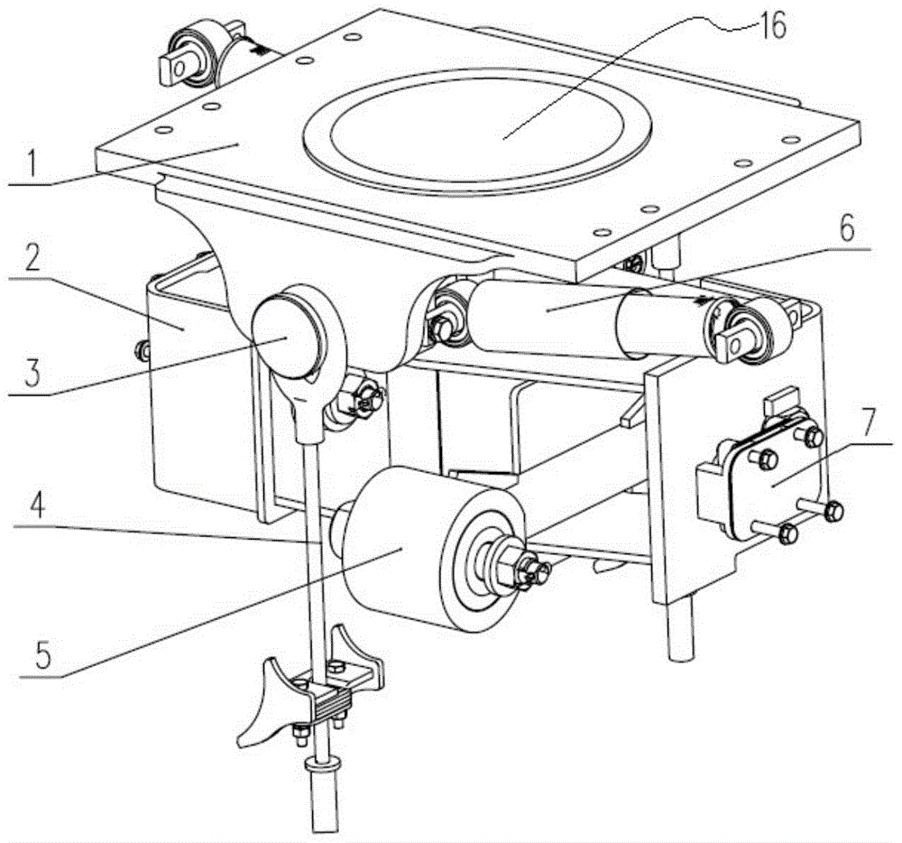
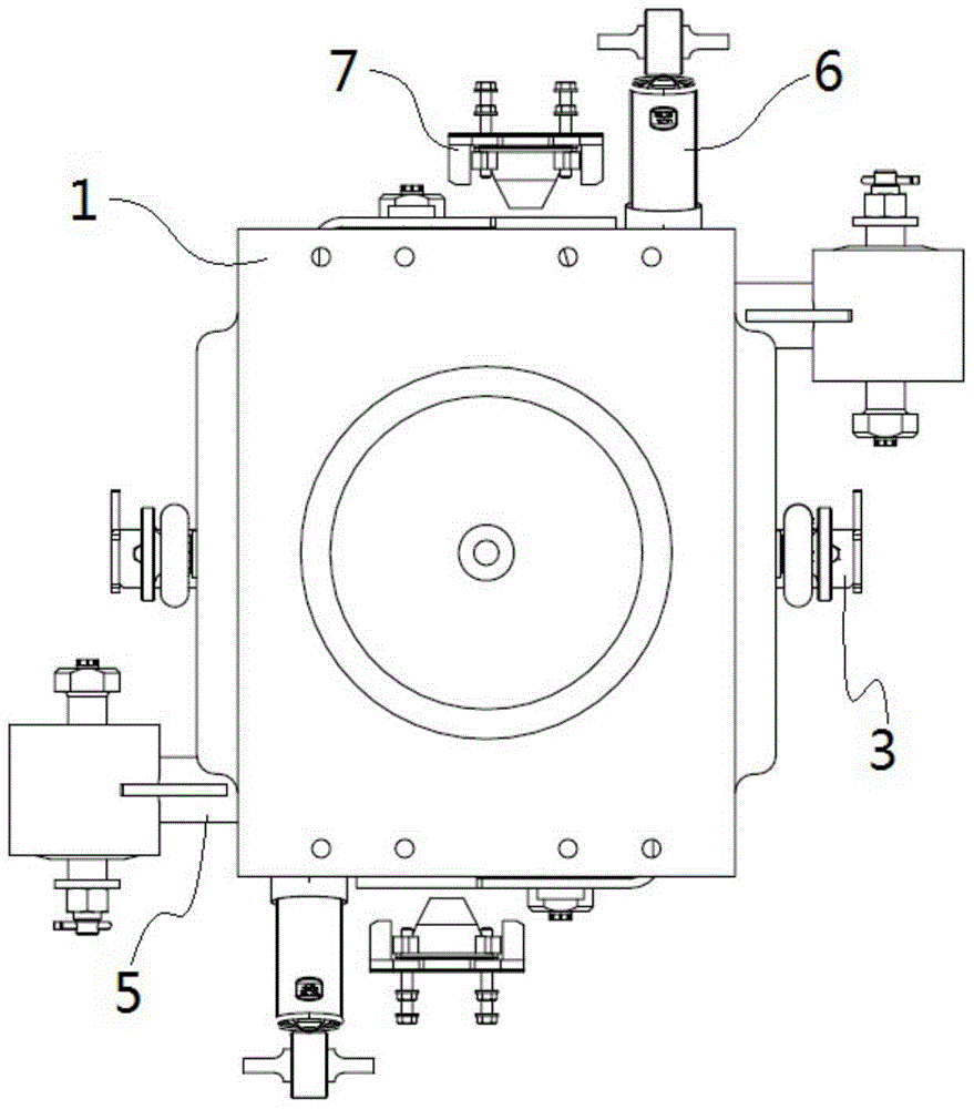
[0030] A multifunctional compact center pin traction device, such as figure 2 As shown, the traction device is mainly composed of a center pin base 1, a traction base 2, a lifting pin 3, a lifting wire rope 4, a traction rod assembly 5, a lateral shock absorber 6, a lateral stop 7, and the like.

[0031] Such as Figure 4 As shown, the center pin seat 1 is a hollow integral structure with a center revolving hole 16. The upper end is connected to the vehicle body through bolts, and the lower end is connected to the traction seat through a traction rubber tube, which plays the role of transmitting traction and braking force, and can Adapt to the rotation of the car body relative to the bogie. There are two horizontal shock absorber mounts on the center pin seat for absorbing lateral vibration. The central revolving hole 16 is surrounded by an annular boss extending upward at least 10 mm, and the annular boss cooperates with the end of the vehicle body to form a stop structure.

[0...


PUM


Abstract

The invention discloses a multifunctional compact traction device for a center pin. The traction device comprises a center pin seat, a traction base connected with the center pin seat, a traction bar assembly installed on the traction base and transverse absorbers, wherein the lower parts of the center pin seat are provided with two absorber seats as rib plates, the absorber seats are provided with transverse absorbers; the traction seat is a semi-closed structure used for enveloping the traction bar, and the left side plate and right side plate of the traction seat are provided with transverse backstops. According to the multifunctional compact traction device provided by the invention, the structure can be simplified and the functions of the traction devices can be enriched; furthermore, the problems that the traction seat is large in welding quantity, the center pin seat is single in function and the interference is likely to be caused can be solved to a large extent.

Description

Technical field [0001] The invention relates to a rail transit vehicle bogie traction device, in particular to a multifunctional compact center pin traction device. Background technique [0002] The traction device is widely used as a longitudinal connection device at home and abroad. On various types of railway freight cars and passenger cars, the traction device mainly connects the car body and the frame, transmits traction and braking force, and adapts to the rotation of the car body relative to the bogie. [0003] Chinese patent CN201020135665.0 discloses a compact traction device with a center pin seat and a Z-shaped tie rod structure, such as figure 1 As shown, the structure is mainly composed of the center pin seat assembly 1, the transverse damper seat 8, the traction seat assembly 2, the traction rod assembly 5, the transverse stop 7, the transverse damper 6, and so on. This kind of traction device has a compact structure and saves installation space, but this kind of trac...

Claims


Application Information

Patent Timeline
Patent Type & Authority Patents(China)
IPC IPC(8): B61F5/18B61G9/04
CPCB61F5/18
Inventor 颜志军喻佳文陈喜红陶功安晋军辉
Owner ZHUZHOU ELECTRIC LOCOMOTIVE CO LTD
Why Eureka
Try Eureka