Method for reducing water pollution of optical elements in immersion type photoengraving technology

A technology of immersion lithography and optical components, applied in the direction of microlithography exposure equipment, optical, electrical components, etc., can solve the problems of reducing expressiveness and eroding optical components, and achieve the effect of protection from erosion

Inactive Publication Date: 2007-07-11
SHANGHAI INTEGRATED CIRCUIT RES & DEV CENT +1
View PDF4 Cites 0 Cited by
  • Summary
  • Abstract
  • Description
  • Claims
  • Application Information

AI Technical Summary

Problems solved by technology

The main problem is the interaction of photosensitive materials. Substances are released from photosensitive materials and penetrate into the liquid. In the subsequent exposure process, they will affect the material at the bottom of the lens, and then erode the optical components and reduce their expressiveness.

Method used


Image

  • Method for reducing water pollution of optical elements in immersion type photoengraving technology

Examples


Embodiment Construction

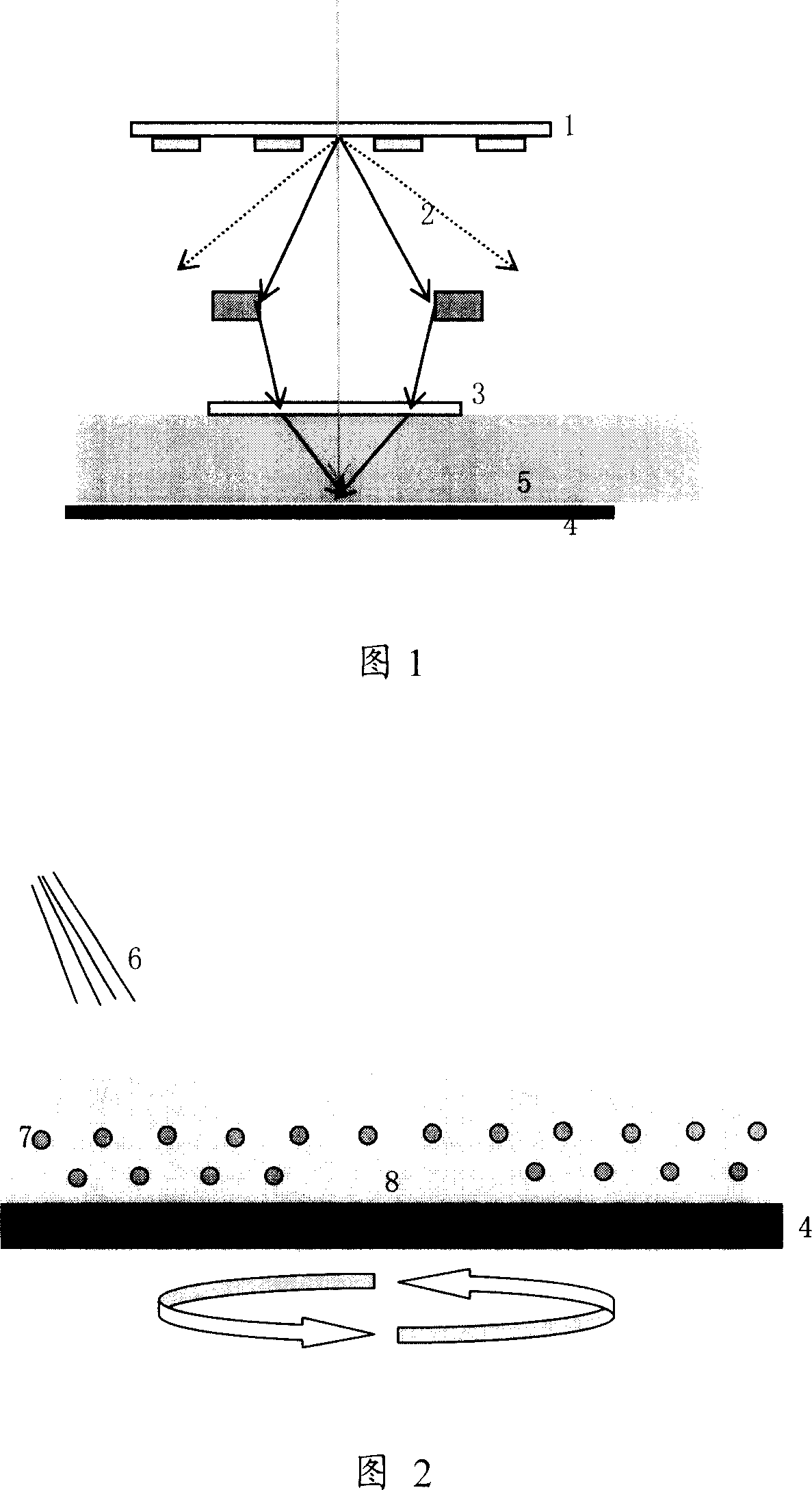
[0029] A method to reduce the contamination of optical components by aqueous solution in immersion lithography technology. First, the silicon wafer enters the glue coating equipment and coats the photosensitive material. The photosensitive material includes ketones or ethers or alkane organic solvents, photosensitive crosslinking resins, photoacid generators and trace metal ions, the molecular weight is between 85000 and 150000, the organic solvent and photosensitive crosslinking resins and photoacid generators The molar ratio is 1:X:Y, wherein X and Y are 5-100, for example, the ratio is set as 1:20:50, 1:40:100, etc. Each coating dose is 1.5ml, 2ml, 3ml, 4ml or 5ml; each baking temperature is 60°C, 100°C, 120°C, 150°C or 250°C, and the baking time is 10 seconds, 30 seconds, 50 seconds, 80 seconds or 120 seconds; the cooling temperature is 15°C, 20°C, 23°C or 25°C, and the cooling time is 20 seconds, 30 seconds, 40 seconds, 50 seconds or 60 seconds.

[0030] Next, rinse the ...


PUM


Abstract

The invention relates to the method of reducing water solution contamination to optical component through optimization process, adding surface active fluid to pre wetting the silicon before it dipping into the optical etching equipment and contacting with water, removing additional optical acid generator or other surface contamination, greatly reducing contamination of water solution with improved evenness of the silicon image.

Description

technical field [0001] The invention relates to the technical field of integrated circuit manufacturing technology, in particular to a method for reducing the contamination of optical components by aqueous solution in immersion photolithography technology. Background technique [0002] With the continuous improvement of integrated circuit manufacturing technology and the continuous shrinking of line width, the area of ​​semiconductor devices is becoming smaller and smaller. The layout of semiconductors has evolved from ordinary single-function separation devices to integrated high-density and multi-functional integrated circuits; From the initial integrated circuit (IC) to large-scale integration (LSI), very large-scale integration (VLSI), and today's ultra-large-scale integration (ULSI), the area of ​​the device is further reduced, and the functions are more comprehensive and powerful. Considering the complexity of process research and development, long-term and high cost a...

Claims


Application Information

Patent Timeline
Patent Type & Authority Applications(China)
IPC IPC(8): G03F7/20G03F7/00H01L21/027
Inventor 朱骏
Owner SHANGHAI INTEGRATED CIRCUIT RES & DEV CENT
Why Eureka
Try Eureka