Indoor decoration wall tile laying device

A technology of laying device and interior decoration, applied in the direction of construction and building structure, can solve the problems of uneven cement application, cumbersome process of placing wall tiles, and low accuracy of manual installation, so as to reduce manual labor, reduce cumbersome processes, and improve The effect of laying efficiency

Active Publication Date: 2020-07-17
马鞍山宏合建筑工程有限公司
9 Cites 12 Cited by

AI-Extracted Technical Summary

Problems solved by technology

[0004] (1) When laying wall tiles by manual laying, usually the rough surface of the wall tiles is first covered with cement manually, and then the wall tiles are positioned and laid manually. The position of the final wall tiles is regular, and it is necessary to ensure that the pasted wall tiles will not produce hollows, which makes the manual installation accuracy low, thereby reducing the efficiency of wall tile laying;
[0005] (2) When the existing indoor wall tile laying device is laying decorative wall tiles, the existing indoor wal...

Abstract

The invention relates to an indoor decoration wall tile laying device. The indoor decoration wall tile laying device includes a moving device, two side plates, a feeding device, laying device bodies and plastering devices. The side plates are front and back symmetrically installed on the middle part of the upper end of the moving device, the feeding device is installed at the upper ends of the side plates by welding, the laying device bodies are laid below the feeding device, and the laying device bodies are installed in the side plates, and the plastering devices are arranged at the left endsof the laying device bodies. According to the indoor decoration wall tile laying device, the problems that the laying process is cumbersome and the manual installation accuracy is low due to the factthat when laying is carried out manually, the rough surface of a wall tile is plastered with cement manually, and then the wall tile is positioned and laid manually; and the laying efficiency of thewall tile is reduced due to the fact that when laying is carried out by an existing indoor wall tile laying device, the wall tile is manually placed on the wall tile laying device for locking and fixing, and then the rough surface of the wall tile is plastered with cement, the plastering of the cement is uneven during laying, wall tile laying produces hollowing, and the process of manual placing of the wall tile is cumbersome can be solved.

Application Domain

Technology Topic

Rough surfaceStructural engineering +3

Image

  • Indoor decoration wall tile laying device
  • Indoor decoration wall tile laying device
  • Indoor decoration wall tile laying device

Examples

  • Experimental program(1)

Example Embodiment

[0033] In order to make the technical means, creative features, objectives and effects of the present invention easy to understand, the following is combined Figure 1 to Figure 7 , To further explain the present invention.
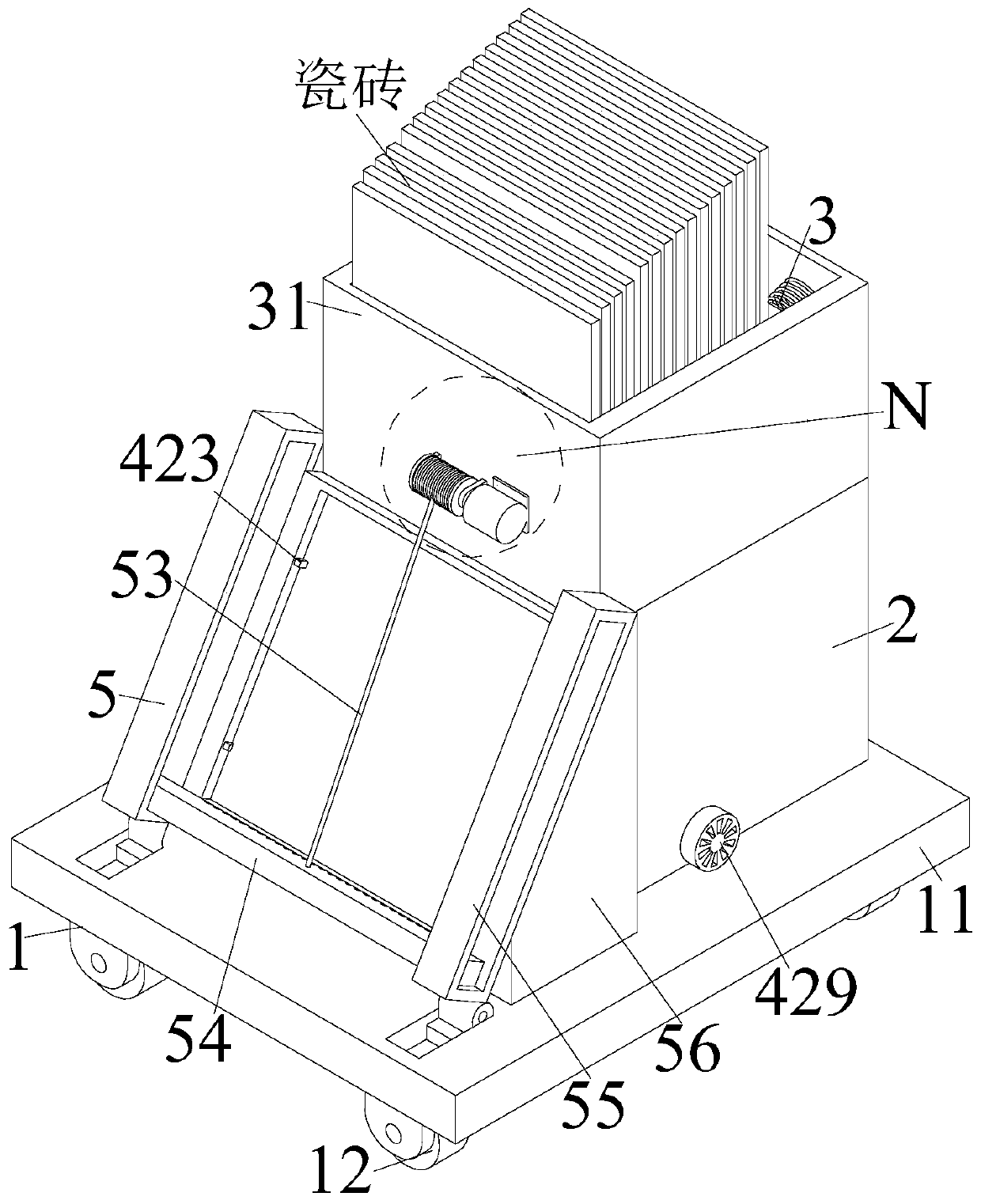
[0034] A paving device for indoor decoration and decorative wall tiles includes a moving device 1, two side plates 2, a feeding device 3, a paving device 4 and a plastering device 5. The upper middle of the moving device 1 is symmetrically installed with side plates 2 back and forth. A loading device 3 is installed at the upper end of the side board 2 by welding, a laying device 4 is installed under the loading device 3, and the laying device 4 is installed inside the side board 2, and a plastering device 5 is installed at the left end of the laying device 4;
[0035] The mobile device 1 includes a mounting plate 11 and four moving wheels 12, and moving wheels 12 are installed at the four corners of the lower end of the mounting plate 11, and the moving wheels 12 are installed symmetrically. During specific work, the mounting plate 11 is manually pushed. The moving wheel 12 drives the equipment to move, so that tiles are laid in sequence.
[0036] The loading device 3 includes a stacking mechanism 31 and a blanking mechanism 32. The stacking mechanism 31 is installed on the upper end of the side plate 2 by welding, and the blanking mechanism 32 is installed at the middle of the lower end of the stacking mechanism 31 by welding. During work, multiple tiles are manually placed on the stacking mechanism 31 at a time, so that the laying device 4 drives the blanking mechanism 32 to sequentially unload and lay the stacked tiles.
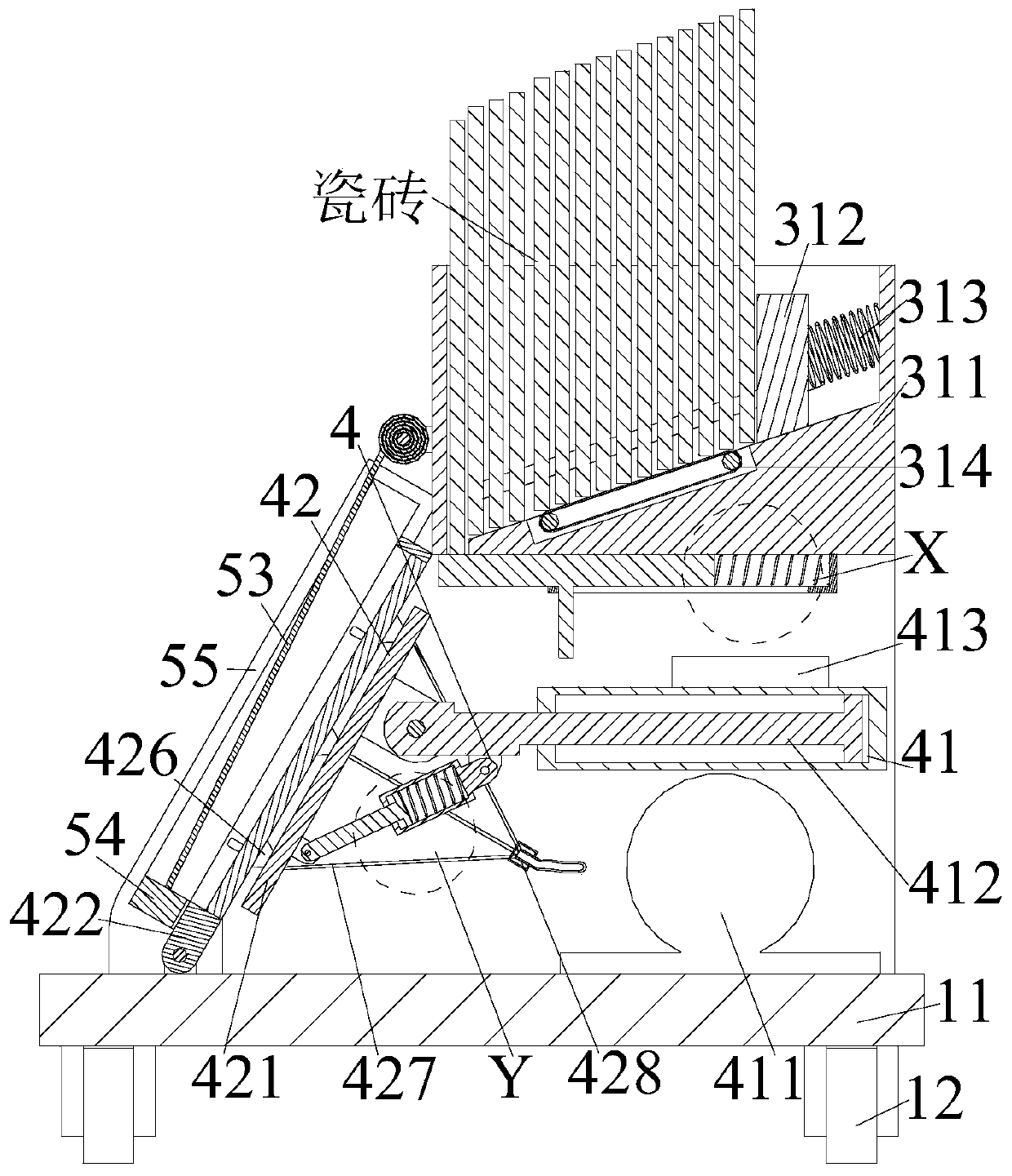
[0037] The coding mechanism 31 includes a loading frame 311, a loading block 312, three loading springs 313 and a transmission belt 314. The loading frame 311 is installed on the upper end of the side plate 2 by welding, and the inside right end of the loading frame 311 is set There is a loading block 312. The front and rear ends of the loading block 312 are symmetrically installed with dovetail blocks. The dovetail blocks are installed in the loading frame 311 by sliding fit. The right end of the loading block 312 is connected to the loading frame 311 through a loading spring 313. , And the loading spring 313 is evenly arranged from the front to the back. The loading spring 313 acts as a locking limit. The middle of the lower end of the loading frame 311 is equipped with a transmission belt 314 through a bearing. During specific work, multiple tiles are placed manually at a time In the loading frame 311, the loading spring 313 is made to press the loading block 312 to ensure that the tiles are always in a vertical state, and the tiles are transferred forward through the conveyor belt 314, so that the tiles are sequentially loaded.
[0038] The lower end of the inner side of the loading frame 311 is a structure inclined from right to left, and the conveyor belt 314 is also arranged inclined from right to left, and the loading frame 311 and the conveyor belt 314 are inclined downward from right to left. , So that the tiles move to the left due to their own gravity, so that they are sequentially loaded.
[0039] The blanking mechanism 32 includes a square sleeve 321, a sealing plate 322, and a sealing spring 323. The square sleeve 321 is installed in the middle of the lower end of the loading frame 311 by means of a welding machine, and the inside of the square sleeve 321 is installed with a seal through a sliding fit. Stop plate 322. The right end of the sealing plate 322 is connected to the square sleeve 321 through a sealing spring 323. The sealing spring 323 functions as a buffer, shock absorption and resetting. During specific work, the sliding plate 421 is driven to move to the right by the drive mechanism 41 to make it slide The upper end of the plate 421 clamps the sealing plate 322, thereby driving the sealing plate 322 to squeeze the sealing spring 323 to move to the right, so that the tiles in the loading frame 311 fall onto the sliding plate 421 due to their own gravity to complete the loading. After the completion, the sealing plate 322 is driven to reset by the sealing spring 323, so that the sealing plate 322 seals the inside of the loading frame 311 to prevent the second tile from falling.
[0040] The laying device 4 includes a driving mechanism 41, a laminating mechanism 42, and a supporting mechanism 43. The driving mechanism 41 is installed at the right end of the moving device 1, and the left end of the driving mechanism 41 is mounted with a laminating mechanism 42 through a hinge. The laminating mechanism 42 and the driving mechanism 41 A supporting mechanism 43 is installed between the hinges. During specific work, the blanking mechanism 32 is driven to move to the left by the driving mechanism 41, so that the stacked tiles fall onto the laminating mechanism 42, so that the laminating mechanism 42 drives the tile to move to the left. The plastering device 5 is made to plaster the rough surface of the tile to be laid. After the plastering is completed, the driving mechanism 41 drives the laminating mechanism 42 to rotate so that the tile is attached to the wall. During the laminating process, the supporting mechanism 43 is attached to the The bonding mechanism 42 performs support and fixation. After the tile bonding is completed, the bonding mechanism 42 unlocks and relaxes the tile after the bonding is completed, and the next tile is laid.
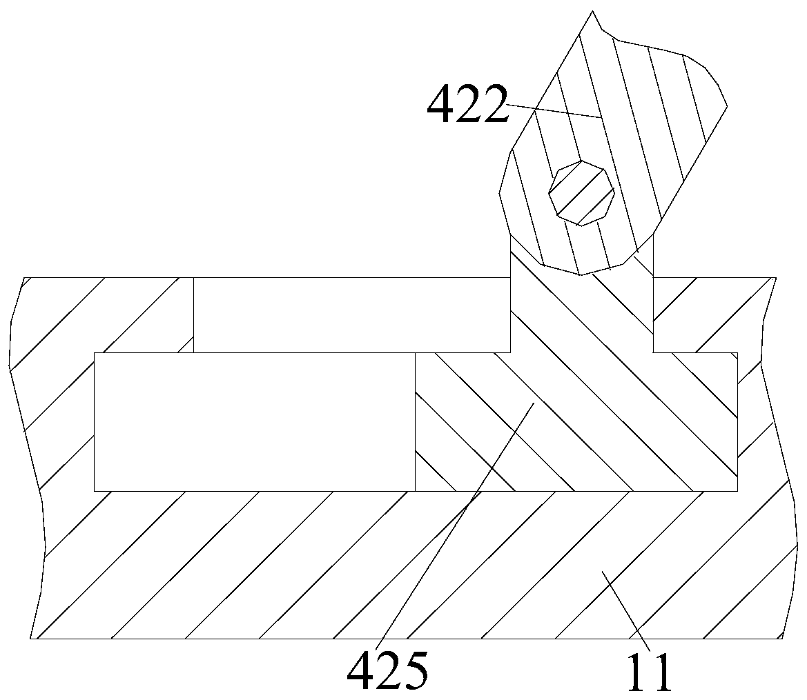
[0041] The fitting mechanism 42 includes a sliding plate 421, a rotating frame 422, a clamping block 423, a clamping spring 424, a sliding block 425, a suction cup 426, a gas pipe 427, a vent valve 428 and a vent handle 429. The sliding plate 421 is mounted on the cylinder through a hinge. At the extended end of 412, a rotating frame 422 is provided on the left side of the sliding plate 421. A clamping block 423 is installed inside the rotating frame 422 through a sliding fit. The inside of the clamping block 423 is connected to the rotating frame 422 through a clamping spring 424, and the clamping spring 424 It plays the role of locking and fixing and resetting. The lower end of the rotating frame 422 is equipped with a sliding block 425 through a hinge. The sliding block 425 is installed on the left side of the upper end of the mobile device 1 by a sliding fit. The left end of the sliding plate 421 is evenly arranged with suction cups 426 and suction cups 426. An air pipe 427 is installed at the right end, and the air pipe 427 is connected to the air vent valve 428. The air vent handle 429 is installed at the front end of the air vent valve 428. During specific work, the driving mechanism 41 drives the blanking mechanism 32 to move to the left, so that the stacked tiles fall to the sliding plate 421. Up, so that the suction cup 426 locks and fixes the tiles. After the tiles are locked and fixed, the drive mechanism 41 drives the sliding plate 421 to move to the left, so that the tiles are locked into the rotating frame 422, and the locking block 423 is locked to the left end of the tiles, and the tiles are stuck. Then, the rough surface of the tile to be laid is plastered by the plastering device 5. After the plastering is completed, the driving mechanism 41 drives the sliding block 425 and the rotating frame 422 to rotate, so that the tile squeezes the block 423, so that the sliding block 425 drives The tiles are separated from the rotating frame 422 and laid on the wall. After the tiles are laid, the vent handle 429 is manually rotated, so that the vent valve 428 puts the gas into the suction cup 426 through the trachea 427, so that the suction cup 426 unlocks and relaxes the tile after the bonding is completed After the tiles are unlocked and relaxed, the driving mechanism 41 drives the sliding plate 421 to move to the right, so as to lay the next tile.
[0042] The driving mechanism 41 includes an air pump 411, an air cylinder 412, and two support plates 413. The air pump 411 is installed on the right side of the upper end of the mounting plate 11 through a threaded connection. The air pump 411 is provided with an air cylinder 412 at the upper end. The cylinder 412 is connected, and the cylinder 412 is installed inside the side plate 2 through the supporting plate 413, and the supporting plate 413 is arranged symmetrically before and after. During specific work, the air pump 411 drives the air cylinder 412 to move, so that the air pump 411 drives the sliding plate 421 to move, so that the sliding plate 421 Load and unload the tiles.
[0043] The support mechanism 43 includes a support sleeve 431, a support rod 432, and a support spring 433. The support sleeve 431 is mounted on the lower end of the left side of the extension end of the cylinder 412 through a hinge. The support sleeve 431 is fitted with a support rod 432 through a sliding fit. The left end of the rod 432 is hinged to the lower right end of the sliding plate 421, and the right end of the support rod 432 is connected to the support sleeve 431 through the support spring 433. During specific work, when fitting, the support rod 432 presses the support spring 433 inward along the support sleeve 431 , So that the sliding plate 421 and the rotating frame 422 are in the vertical position, so that the sliding plate 421 lays the tiles. After the laying is completed, the sliding plate 421 moves to the right, and the support spring 433 drives the support rod 432 to reset, so that the sliding plate 421 is reset. Load the next tile.
[0044] A sliding groove is provided on the left side of the mounting plate 11, and the sliding block 425 is installed in the sliding groove by a sliding fit. During specific work, the sliding block 425 moves along the sliding groove to limit and guide the rotating frame 422 and slide When the block 425 moves to the left end of the sliding groove, the driving mechanism 41 drives the rotating frame 422 to rotate around the sliding block 425 to a vertical position. When the rotating frame 422 is in the vertical position, the driving mechanism 41 drives the tile pressing block 423, so that the tile is separated from the rotation The frame 422 is attached to the wall surface.
[0045] The plastering device 5 includes a rotating motor 51, a rope drum 52, a steel wire 53, a plastering board 54, two guide frames 55 and two trapezoidal plates 56. The rotating motor 51 is installed at the middle of the left end of the stacking mechanism 31 through a motor mounting plate. , The output end of the rotating electric machine 51 is installed with a rope drum 52 by welding, the rope drum 52 is installed on the stacking mechanism 31 through a bearing, a wire rope 53 is wound on the rope drum 52, and a plastering board 54 is installed at the lower end of the wire rope 53. The front and rear ends of the plate 54 are symmetrically provided with a guide frame 55. The guide frame 55 is installed on the mobile device 1 through a trapezoidal plate 56, and the plastering board 54 is installed in the guide frame 55 by a sliding fit. During specific work, the tiles are stuck in After the frame 422 is rotated, the mixed cement is manually placed on the upper end of the plastering board 54. After the cement is placed, the rotary motor 51 is rotated to make the rope drum 52 rotate around the steel wire 53 so that the steel wire 53 drives the plastering board 54 Ascend along the guide frame 55, so that the plastering board 54 evenly spreads the cement on the tiles to be laid, so that the tiles are attached to the wall surface. After the tiles are attached, the driving mechanism 41 drives the sliding board 421 to move to the right and pass The rotating motor 51 drives the rope drum 52 to rotate, so that the steel wire 53 is relaxed, so that the plastering board 54 is lowered and reset along the guide frame 55 due to its own gravity to plaster the next tile.
[0046] The right end of the plastering board 54 is uniformly provided with semi-circular grooves. The semi-circular grooves make the plastering board 54 evenly spread cement on the tiles, avoiding hollowing between the laminated tiles and the wall due to uneven application of cement.
[0047] in working:
[0048] S1. Placing tiles: manually placing multiple tiles in the loading frame 311 at a time, so that the loading spring 313 squeezes the loading block 312 to ensure that the tiles are always in a vertical state, and the tiles are transferred forward through the conveyor belt 314;
[0049] S2. Feeding: The air pump 411 drives the sliding plate 421 to move to the right, so that the upper end of the sliding plate 421 clamps the sealing plate 322, thereby driving the sealing plate 322 to squeeze the sealing spring 323 to move to the right, so that the loading frame 311 The tiles fall onto the sliding plate 421 due to their own gravity to complete the loading;
[0050] S3. Spreading cement: manually place the mixed cement on the upper end of the plastering board 54 and rotating the rotary motor 51 to make the rope drum 52 rotate around the steel wire rope 53, so that the steel wire 53 drives the plastering board 54 up along the guide frame 55, and then Make the plastering board 54 evenly spread the cement on the tiles to be laid;
[0051] S4. Laying: The air pump 411 drives the sliding block 425 and the rotating frame 422 to rotate, so that the rotating frame 422 is in a vertical position, and the sliding block 425 continues to move to the right, causing the tile to squeeze the block 423, so that the sliding block 425 drives the tile out of rotation Frame 422 is laid on the wall;
[0052] S5. Cutting: After the tiles are laid, manually rotate the vent handle 429 so that the vent valve 428 puts the air into the suction cup 426 through the air pipe 427, so that the suction cup 426 unlocks and relaxes the tile after the bonding is completed.
[0053] The above shows and describes the basic principles, main features and advantages of the present invention. Those skilled in the industry should understand that the present invention is not limited by the above embodiments. The above embodiments and the description in the specification only illustrate the principles of the present invention. Without departing from the spirit and scope of the present invention, the present invention will also There are various changes and improvements, and these changes and improvements fall within the scope of the claimed invention. The scope of protection claimed by the present invention is defined by the appended claims and their equivalents.

PUM

no PUM

Description & Claims & Application Information

We can also present the details of the Description, Claims and Application information to help users get a comprehensive understanding of the technical details of the patent, such as background art, summary of invention, brief description of drawings, description of embodiments, and other original content. On the other hand, users can also determine the specific scope of protection of the technology through the list of claims; as well as understand the changes in the life cycle of the technology with the presentation of the patent timeline. Login to view more.

Similar technology patents

Electric energy meter turnover box clamping mechanism

ActiveCN102662156AAvoid manual operationsReduce manual laborElectrical measurementsElectric energy
Owner:CHONGQING ELECTRIC POWER RES INST +2

Classification and recommendation of technical efficacy words

  • Reduce manual labor
  • Reduce cumbersome process

Assembly equipment for electromagnet core

InactiveCN108091476AReduce manual laborReduce the cost of the provincial capitalManufacturing stator/rotor bodiesMagnetic core manufactureMechanical equipmentElectromagnet
Owner:ZHEJIANG UNIV OF TECH FENGHUA SMART ECONOMY RES INST

Method for preparing hierarchical porous titanium silicalite TS-1

InactiveCN101962195ALower synthesis costReduce cumbersome processCrystalline aluminosilicate zeolitesMolecular sieveCarbon nanotube
Owner:DALIAN UNIV OF TECH

Terminal control method, terminal control device and terminal equipment

ActiveCN106878550AReduce cumbersome processSolve the cumbersome operationDigital data authenticationSubstation equipmentAge groupsUser experience design
Owner:QIKU INTERNET TECH SHENZHEN CO LTD

Projector device with theft prevention function and theft preventing method

InactiveUS20060164242A1Reduce cumbersome processElectric signalling detailsBurglar alarm by hand-portable articles removalDouble integratorEngineering
Owner:NEC DISPLAY SOLUTIONS LTD
Why Eureka
Try Eureka