A pump in the middle water inlet pipe

A water inlet pipe and water inlet technology, applied in the direction of pumps, pump components, pump devices, etc., can solve the problems of inconvenient operation of valves at the water outlet, occupying a large area, and occupying a large space for motors, which is beneficial to operation and maintenance, and reduces manufacturing costs. cost, and the effect of improving water intake efficiency

Active Publication Date: 2021-02-19
涂程光
View PDF0 Cites 0 Cited by
  • Summary
  • Abstract
  • Description
  • Claims
  • Application Information

AI Technical Summary

Problems solved by technology

Since the water inlet of the deep well submersible pump is located in the middle between the motor and the pump body, and the characteristics of the conventional pump in the pipe, one end of the water inlet and the other end of the water outlet, the water inlet and the motor share the water flow channel, and the motor occupies a large space, which leads to the casing of the pump in the pipe. The diameter is correspondingly enlarged, and the water inlet efficiency is not high. There is still room for optimization of the pump body of the pump in the pipe; the pump body of the pump in the pipe is thin and long, and the height of the pump is often too high when it is installed vertically, especially in high-lift applications. , plus the installation height of other pipe fittings and valves, it is even necessary to increase the floor height of the pump room, and it is inconvenient to operate the valve at the water outlet; when it is installed horizontally, it occupies too much space, occupying the plane space of the pump room and is easy to wear the bearings

Method used


Image

  • A pump in the middle water inlet pipe
  • A pump in the middle water inlet pipe
  • A pump in the middle water inlet pipe

Examples


Embodiment 1

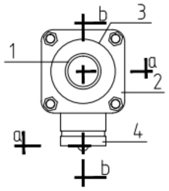
[0041] combined with Figure 1~4 , this embodiment is a single-stage pump body structure with a conventional vertical installation method. The connection relationship and related structure of each component from top to bottom are: the upper end of the water outlet transfer interface 1 is provided with a groove for connecting external pipes, and the water outlet The lower end of the adapter 1 is provided with a threaded interface for connecting to the deep well submersible pump. The middle part of the water outlet adapter 1 is welded with an inner and outer flange 2, through which the inner and outer flange 2 and the fastening seal (bolt) and the casing 3 are connected. The top is connected, and the outer wall of the middle part of the casing 3 has a round hole and is welded with a radial water inlet 4. The water inlet 4 is a horizontal pipe with a groove connection. Divide the water inlet section into two parts, upper, lower, and lower, and weld the diversion partition 5. Thre...

Embodiment 2

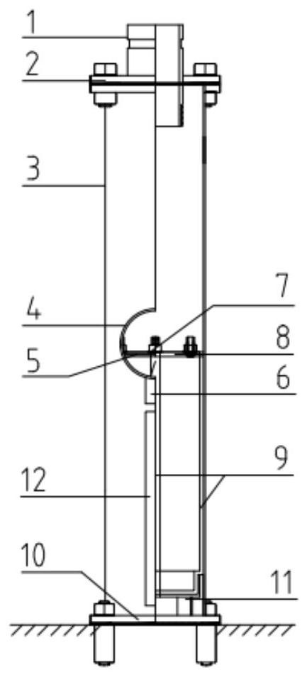
[0043] combined with Figure 5-8, this embodiment is a two-stage pump body structure in a vertical semi-buried installation mode. The connection relationship of each component from top to bottom and the related structure are: the upper end of the water outlet transfer interface 1 is provided with a groove for connecting external pipes, The lower end of the water outlet transfer interface 1 is provided with a threaded interface for connecting the deep well submersible pump. The middle part of the water outlet transfer interface 1 is welded with an annular plate, and the outer ring of the annular plate is welded to the upper end of the pump casing 31. The pump casing 31 is set in the deep well. Outside the pump body of the submersible pump, the outer wall of the lower part of the casing 31 of the pump body is perforated and welded with a radial water inlet 4. The water inlet 4 is a horizontal pipe with a groove connection. There is a diversion baffle 5 that divides the water inl...

Embodiment 3

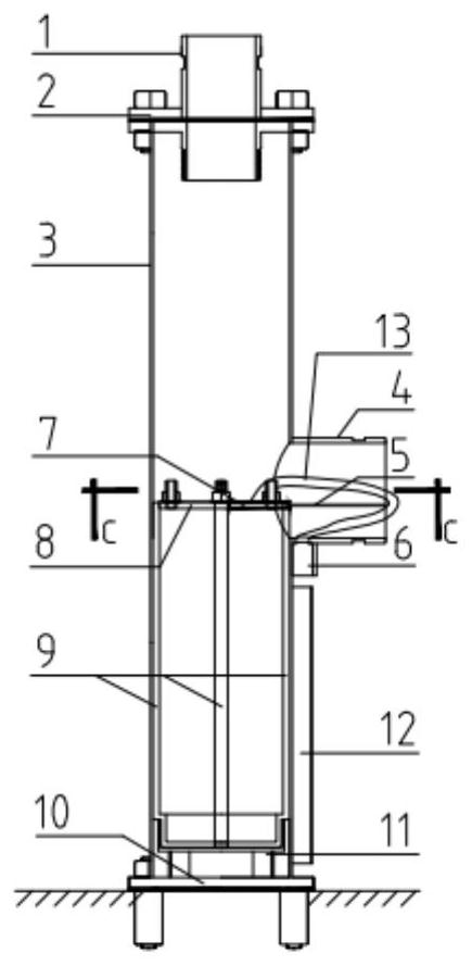
[0045] combined with Figure 9-15 , this embodiment is an ordinary vertically installed three-stage pump body structure, and the advantage of this structure is that it is more convenient for large-scale mass production. In this embodiment, the original water inlet 4 is made into a three-way water inlet 41 in the form of a tee with different diameters. Both ends of the main pipe of the three-way water inlet 41 are welded with a circular seal ring with a sealing surface, and through the pump casing casing 31 and the inner circle and outer flange 2 of the motor sleeve 32, 4 long bolts and two sealing rings to fix the tee water inlet 41 between the pump body sleeve 31 and the motor sleeve 32, and the end blind plate 10 Change it to a flanged end blind plate 14, which is fixed to the ground by expansion bolts and shock absorbing pads. Now because the motor leads are positioned in mid-air, on the outlet hole 6 one side, the outer wall of the motor casing 32 increases the metal wire...


PUM


Abstract

The invention relates to a middle water inflow pump in pipe. The middle water inflow pump in pipe comprises a submersible motor connecting plate and further comprises a water outflow adapter, a roundinside and square outside flange, a fastening sealing part, a sleeve, a water inlet, a guiding partition, a line outlet, a semicircular guiding adhesive tape, the submersible motor connecting plate, U-shaped damping and guiding adhesive tapes, an end blind plate with a flange and an overhead motor support. A groove for being connected with an external pipeline is formed in the upper end of the water outflow adapter, an internal threaded coupling for being connected with a deep well submersible pump is arranged at the lower end of the water outflow adapter, and the round inside and square outside flange is welded to the middle of the water outflow adapter. The two U-shaped damping and guiding adhesive tapes are symmetrically arranged on the outer wall of the motor in the axial direction, and the end blind plate with the flange is arranged at the lower end of the sleeve. The overhead motor support is arranged on the end blind plate with the flange and located in the sleeve. The heat dissipation efficiency of the motor is improved, the pump head is increased, and the middle water inflow pump in pipe can be widely applied to the technical field of water pumps.

Description

technical field [0001] The invention relates to the technical field of water pumps, in particular to a pump in a middle water inlet pipe. Background technique [0002] Due to the natural characteristics of water cooling, the deep well submersible pump makes the heat dissipation efficiency of the motor very high, so that the deep well submersible pump has higher efficiency than other air-cooled water pumps. The pump in pipe is a casing added to the deep well submersible pump, so that it has the characteristics of a conventional water pump. It can be widely used in building water supply and industrial water supply industries. It has the advantages of quietness, energy saving, and flexible installation methods. Although the pump in pipe has many advantages, its disadvantages are also obvious. Since the water inlet of the deep well submersible pump is located in the middle between the motor and the pump body, and the characteristics of the conventional pump in the pipe, one end...

Claims


Application Information

Patent Timeline
Patent Type & Authority Patents(China)
IPC IPC(8): F04D13/08F04D29/00F04D29/40F04D29/60
CPCF04D13/086F04D29/007F04D29/406F04D29/605
Inventor 涂程光
Owner 涂程光
Why Eureka
Try Eureka