
Eureka
For R&D, Eureka makes reading and utilizing patents & technical documents easy.
Eureka AIR
Designed for self-driven R&D workflows. Generate viable solutions, solve complex R&D challenges, empower your innovation with AI.

Eureka Materials
Designed for material experts only. Revolutionize your material R&D, from search, analyze, to developing new materials.

TechResearch
Generate reliable direction feasibility study reports for your R&D in just a few steps.

TechSeek
Discover and master advanced knowledge NOW. Basics, ideas, possibilities, all at once.

TechMind
As an expert in R&D Theories, TechMind can generates customized viable solutions instantly.

TechRisk
Analyze your overall solution with one click, know your potential R&D risks in advance.

TechMonitor
Get weekly tech updates, stay abreast of the latest tech innovations and key insights.
Coded lock and valve with coded lock
A combination lock and lock body technology, which is applied in the field of combination locks and valves with combination locks, can solve the problems of low reliability and poor anti-opening performance, and achieve the effect of simple production and improved anti-opening performance
- Summary
- Abstract
- Description
- Claims
- Application Information
AI Technical Summary
Problems solved by technology
Method used
Image

Examples
Embodiment 1
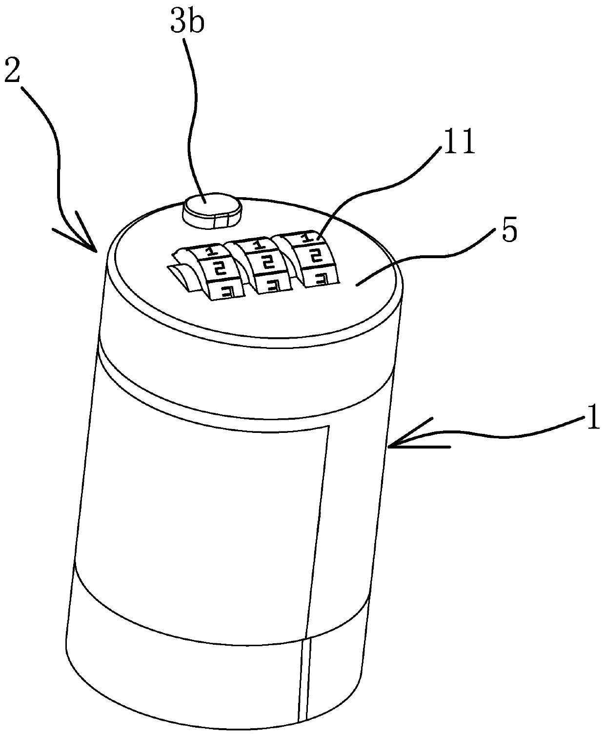
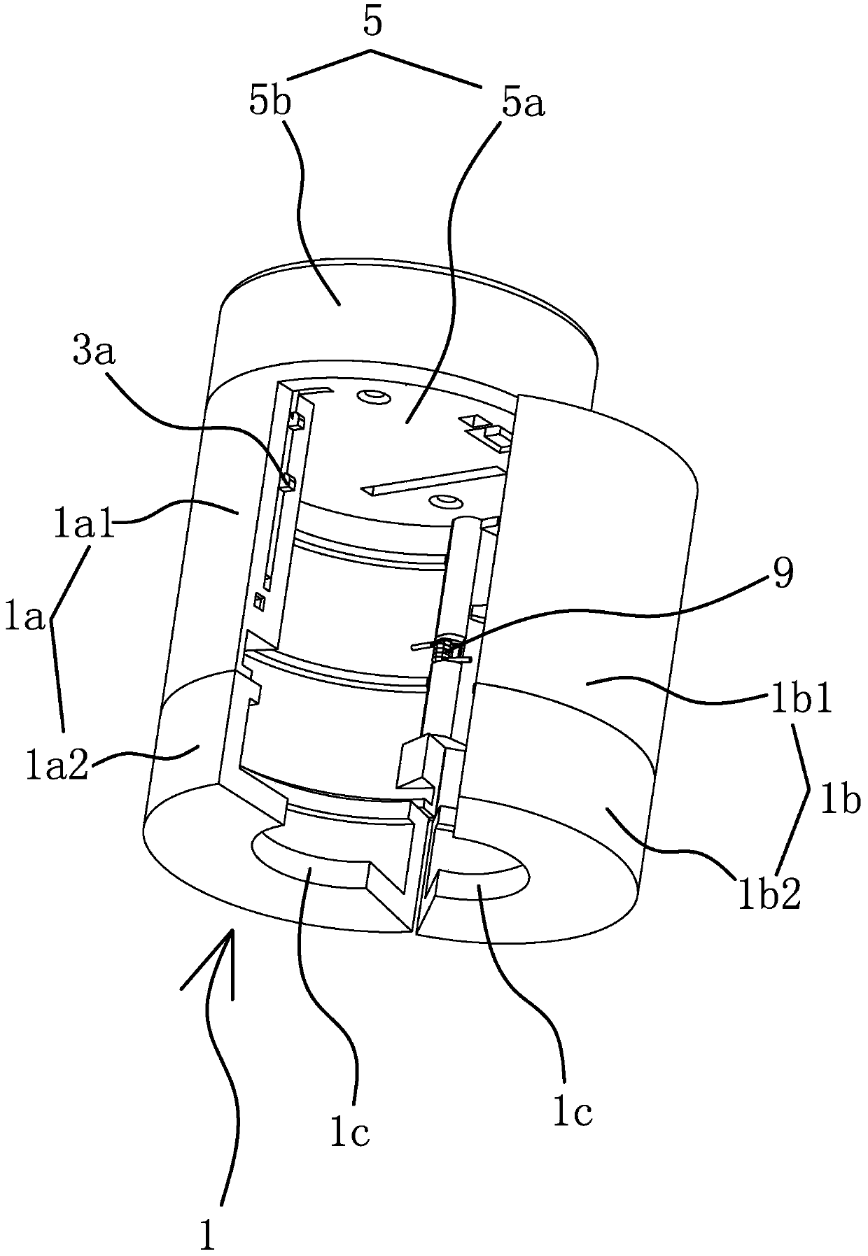
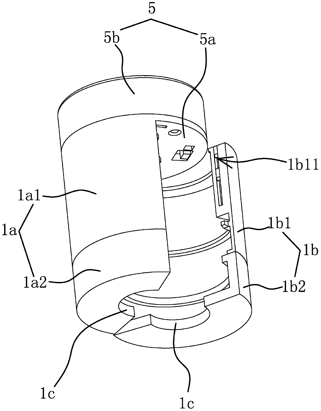
[0045] Such as figure 1 , figure 2 and image 3 As shown, the combination lock includes a lock body 1 and a combination lock box 2 that can control unlocking. The lock body 1 is a cylindrical structure with the upper end closing the lower end opening. The lock body 1 includes a petal body one 1a and a petal body two 1b that can be assembled into a cylindrical structure. The latter is fixed and controlled by the combination lock box 2 locking structure. The first petal body 1a and the second petal body 1b are in the shape of a circular arc plate, the first petal body 1a is hinged to one side of the second petal body 1b, and the locking structure is arranged between the first petal body 1a and the other side of the second petal body 1b. The inner side of the lower end of body one 1a and / or petal body two 1b has a shoulder 1c, and the shoulder 1c is arc-shaped. In this embodiment, the first petal body 1a and the second petal body 1b are semicircular in shape, and both the in...
Embodiment 2
[0054] The structure and principle of this embodiment are basically the same as that of Embodiment 1, the difference is that in this embodiment, the limit mechanism includes a card slot provided on the block 3c and a horizontally protruding set on the upper end of the actuator 8 When the locking wheel 7 rotates until the outer peripheral wall abuts against the protrusion 8a, the locking block can be inserted into the slot so that the dead bolt 3 is fixed. The lower end of the actuator 8 is hinged on the circular top plate 5a, and the elastic member is an unlocking torsion spring arranged at the hinge position between the actuator 8 and the circular top plate 5a.
Embodiment 3
[0056] The inner side of the upper end of petal body one 1a and the inner side of the upper end of petal body two 1b are fixedly connected with a semicircular baffle plate 13b, and the combination lock box 2 is fixed on the outer side of the first petal body 1a and part of the combination lock box 2 stretches out of the outer side of the first petal body 1a. The lock box 2 includes an outer shell 5 and a lock cylinder 6 arranged in the outer shell 5. The lock core 6 includes a rotatable locking wheel 7, and a movable actuator 8 is arranged between the locking wheel 7 and the bottom wall of the outer shell 5. , the actuator 8 is plate-shaped, and the locking structure includes a convex plate vertically connected to the bottom wall of the actuator 8 facing the shell 5 and a locking groove arranged on the outside of the petal body 2 1b. The surface of the actuator 8 facing the locking wheel 7 There is a protrusion 8a on it, and the outer peripheral wall of the locking wheel 7 can ...
PUM
 Abstract
Description
Claims
Application Information
 - R&D Engineer
- R&D Manager
- IP Professional
- Industry Leading Data Capabilities
- Powerful AI technology
- Patent DNA Extraction
Browse by: Latest US Patents, China's latest patents, Technical Efficacy Thesaurus, Application Domain, Technology Topic, Popular Technical Reports.
© 2024 PatSnap. All rights reserved.Legal|Privacy policy|Modern Slavery Act Transparency Statement|Sitemap|About US| Contact US: help@patsnap.com