Lock bar member, lock body, lock component and display screen
A lock rod and lock body technology, applied in the field of locks, can solve problems such as the lock rod cannot be pushed, the user is not very convenient to use, and the lock rod is stuck, so as to achieve the effect of convenient operation and improved operating experience
- Summary
- Abstract
- Description
- Claims
- Application Information
AI Technical Summary
Problems solved by technology
Method used
Image
Examples
Embodiment 1
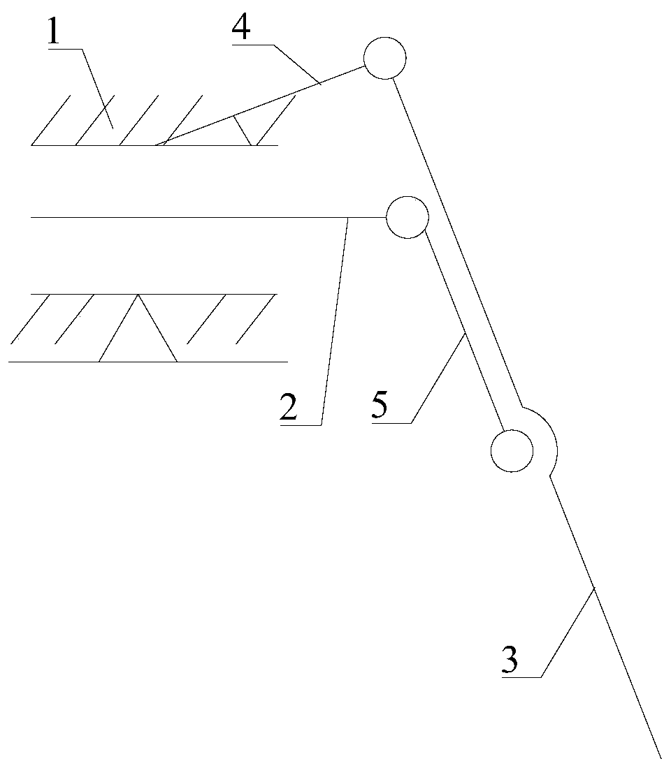
[0079] Please refer to figure 1 , Embodiment 1 of the present invention is: a lock rod, which can be used in a lock assembly, which includes a first positioning sleeve 1, a lock rod 2, a handle 3, a first support rod 4 and a second support rod 5, the lock rod 2 The sliding sleeve is set in the first positioning sleeve 1, the first support rod 4 is fixed on the first positioning sleeve 1 and is hinged with one end of the handle 3, the second support rod 5 is respectively hinged with the locking rod 2 and the handle 3, and the locking rod 2. A lock head is provided at the end away from the second support rod 5.
[0080] The movement of the lock rod in the prior art is a linear motion along its axial direction, and the direction of force application is the same as the direction of its movement. If the force is not enough, it cannot be pushed or jammed. And in the lock bar part of present embodiment is a lever structure substantially, the handle 3 that is provided turns around th...
Embodiment 2
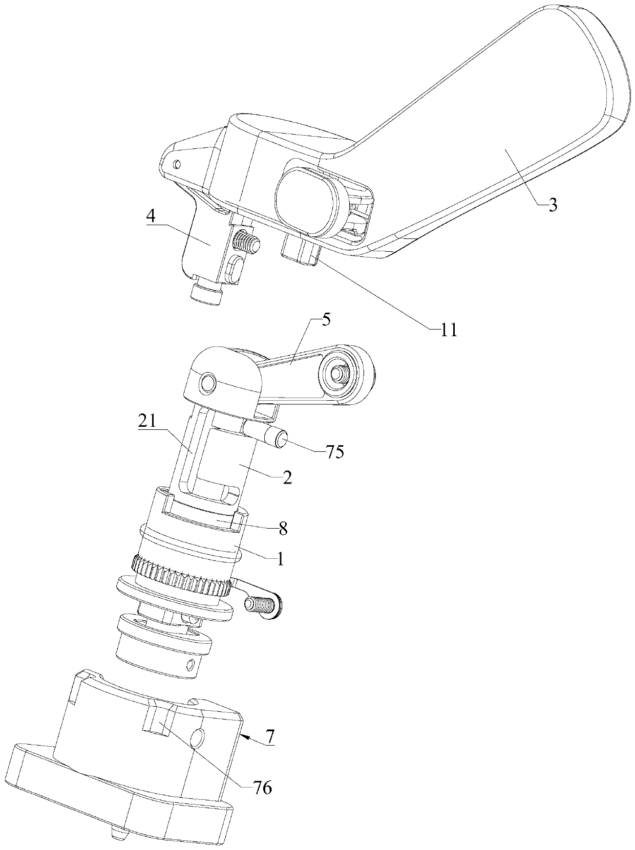
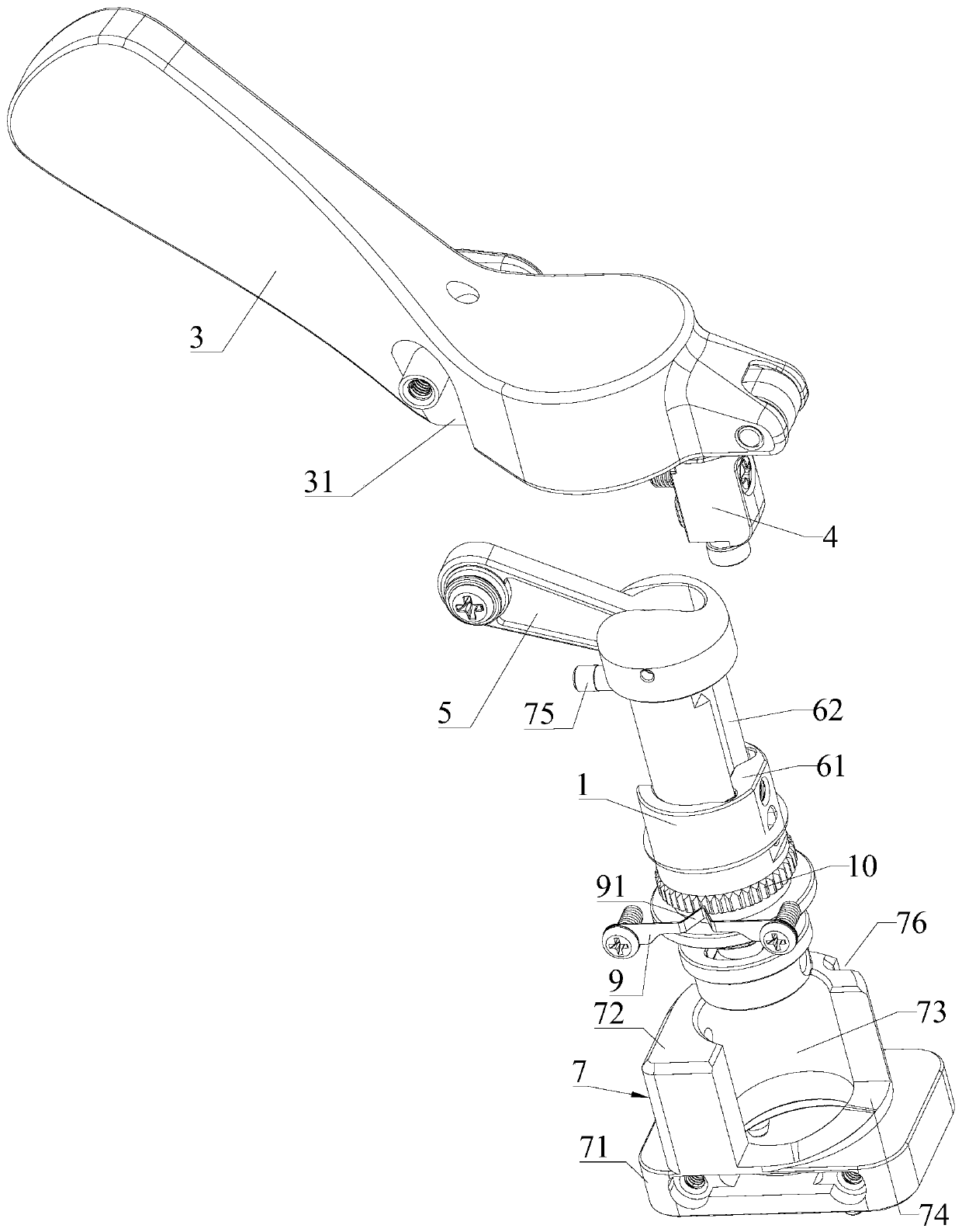
[0087] Please refer to Figure 1 to Figure 5 , the second embodiment of the present invention is: please combine Figure 1 to Figure 3 , a lock body of a lock assembly, comprising a first positioning sleeve 1, a locking rod 2, a handle 3, a first support rod 4, a second support rod 5 and a second positioning sleeve 7, the first positioning sleeve 1 is rotatably set on In the second positioning sleeve 7, the locking rod 2 is slidingly sleeved in the first positioning sleeve 1, the first support rod 4 is fixed on the first positioning sleeve 1 and is hinged with one end of the handle 3, and the second support rod 5 is connected with the lock respectively. The rod 2 and the handle 3 are hinged, and the end of the locking rod 2 away from the second support rod 5 is provided with a lock head. Rotate the handle 3 around the first support rod 4, and at the same time, because the second support rod 5 connects the handle 3 and the lock rod 2 together, the rotation of the handle 3 will...
Embodiment 3
[0098] Please refer to Figure 1 to Figure 10 , the third embodiment of the present invention is: the display screen includes a plurality of frames, and two adjacent frames are connected and fixed by a lock assembly, such as Image 6 with Figure 7 As shown, the lock assembly includes a matching lock body and a lock seat, the lock body is installed on one side of the frame, and the lock seat is installed on the other side of the frame to cooperate with the lock body on the adjacent frame .
[0099] Please combine Figure 1 to Figure 3 , the lock body includes a first positioning sleeve 1, a lock rod 2, a handle 3, a first support rod 4, a second support rod 5 and a second positioning sleeve 7, and the first positioning sleeve 1 is rotatably set on the second positioning sleeve 7, the locking rod 2 is slidingly sleeved in the first positioning sleeve 1, the first supporting rod 4 is fixed on the first positioning sleeve 1 and is hinged with one end of the handle 3, and the s...
PUM
 Abstract
Description
Claims
Application Information
 - R&D
- Intellectual Property
- Life Sciences
- Materials
- Tech Scout
- Unparalleled Data Quality
- Higher Quality Content
- 60% Fewer Hallucinations
Browse by: Latest US Patents, China's latest patents, Technical Efficacy Thesaurus, Application Domain, Technology Topic, Popular Technical Reports.
© 2025 PatSnap. All rights reserved.Legal|Privacy policy|Modern Slavery Act Transparency Statement|Sitemap|About US| Contact US: help@patsnap.com


