Nitrogen cylinder convenient to transport and store

A technology of nitrogen cylinders and sliders, applied in the field of nitrogen cylinders, which can solve problems such as inability to place stably, fall and damage, rolling and rollover of carriages, etc.

Active Publication Date: 2021-04-06
宜春市富锐气体有限责任公司
View PDF9 Cites 1 Cited by
  • Summary
  • Abstract
  • Description
  • Claims
  • Application Information

AI Technical Summary

Problems solved by technology

[0003] However, most of the existing nitrogen cylinders are cylindrical in shape and cannot be placed stably. During transportation, they are prone to rolling

Method used


Image

  • Nitrogen cylinder convenient to transport and store
  • Nitrogen cylinder convenient to transport and store
  • Nitrogen cylinder convenient to transport and store

Examples


Embodiment 1

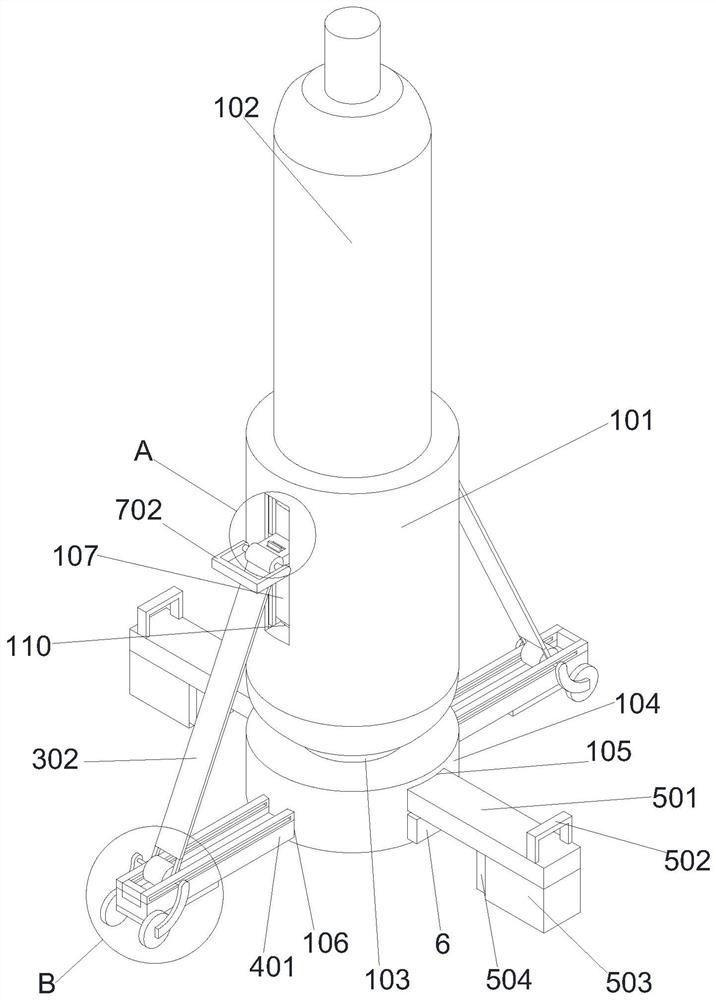
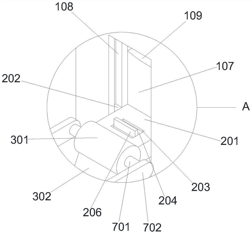
[0023] Example 1: Please refer to Figure 1-Figure 4, the present invention provides a technical solution: a nitrogen cylinder that is convenient for transportation and storage, including a nitrogen cylinder 102, the lower end of the circumferential side of the nitrogen cylinder 102 is fixedly sleeved with a reinforced shell 101, and the center of the lower surface of the reinforced shell 101 is fixedly connected with a Support column 103, the lower surface of support column 103 is fixedly connected with base 104, and the front and rear sides of base 104 are all provided with base through groove 1 105, and the left and right sides of base 104 are all provided with base through groove 2 106, and the left and right sides of reinforcing shell 101 A chute 107 is provided, the front and rear sides of the inner wall of the chute 107 are provided with a chute 108, the upper end of the inner wall of the chute 107 is provided with a card slot 109, and the lower end of the inner wall of ...

Embodiment 2

[0025] Example 2, please refer to figure 1 , on the basis of Embodiment 1, the front end of the lower surface of the bottom support rod 2 501 is fixedly connected with the anti-slip pad 2 503, the upper surface front end of the bottom support rod 2 501 is fixedly connected with the handle 1 502, and the rear side of the anti-slip pad 2 503 is fixed The first magnet 504 is connected, and the lower end of the front and rear sides of the base 104 is fixedly connected with the second magnet 6 .

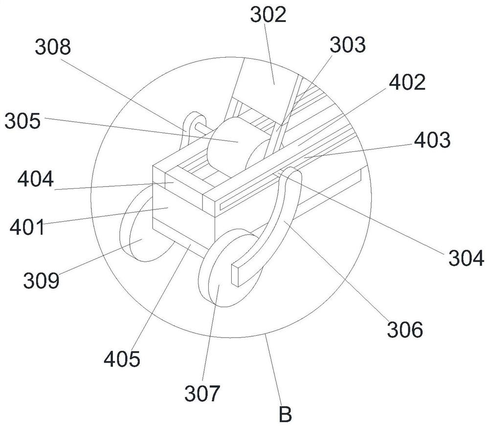
[0026] When in use, on the basis that the bottom support rod one 401 protrudes from the base through groove two 106 and the non-slip pad one 405 touches the ground to improve stability, hold the handle one 502 and push the bottom support rod two 501 from the base through groove one 105 Pull it out to increase the support area, and the contact between the lower surface of the anti-skid pad 2 503 and the ground also increases the friction with the ground, cooperate with the bottom support r...

Embodiment 3

[0027] Example 3: Please refer to figure 1 , figure 2 and Figure 4 , on the basis of the second embodiment, the right end of the outer surface of the second slider 204 is slidably connected to the inner wall of the first slot 109 .

[0028] When in use, buckle the card plate 206 and pull the slider 204 out of the slot 110, then lift the handle 2 702 to make the hollow slider 201 slide upward along the inner wall of the chute 107, and the slider 202 along the The inner wall of the chute 2 108 slides upwards. At this time, the bottom of the moving wheel 1 307 and the moving wheel 2 309 touches the ground again and the bottom support rod 1 401 is jacked up so that the bottom of the anti-skid pad 1 405 is separated from the ground, and then the roller 305 moves along the bottom support rod The upper surface of one 401 rolls, and the support shaft 304 slides along the inside of the through groove 403 to approach the base 104. When the hollow slider 201 moves to the first slot 1...


PUM


Abstract

The invention discloses a nitrogen cylinder convenient to transport and store, and relates to the technical field of nitrogen cylinder equipment. The nitrogen cylinder convenient to transport and store comprises a nitrogen cylinder body, wherein a reinforcing shell fixedly sleeves the lower end of the circumferential side face of the nitrogen cylinder body, a supporting column is fixedly connected to the center of the lower surface of the reinforcing shell, and a base is fixedly connected to the lower surface of the supporting column; base through grooves I are formed in the front side face and the rear side face of the base, and base through grooves II are formed in the left side face and the right side face of the base; sliding grooves I are formed in the left side face and the right side face of the reinforcing shell, sliding grooves II are formed in the front side faces and the rear side faces of the inner walls of the sliding grooves I, clamping grooves I are formed in the upper ends of the inner walls of the sliding grooves I, and clamping grooves II are formed in the lower ends of the inner walls of the sliding grooves I; and hollow sliding blocks are slidably connected to the inner walls of the sliding grooves I, and hinges are fixedly connected to the left side faces of the hollow sliding blocks. The problem that nitrogen cylinders fall down and are damaged due to the fact that the nitrogen cylinders are prone to roll and turn on one side in a compartment during transportation due to the fact that most of existing nitrogen cylinders are cylindrical and cannot be stably placed is solved.

Description

technical field [0001] The invention relates to the technical field of nitrogen cylinder equipment, in particular to a nitrogen cylinder convenient for transportation and storage. Background technique [0002] Nitrogen cylinders, carbon dioxide cylinders, oxygen cylinders, argon cylinders, etc. are steel cylinders made of steel plates, which can contain various non-corrosive gases as long as the specified pressure is not exceeded. Nitrogen cylinders need to be protected during transportation and storage to prevent nitrogen cylinders from falling and being damaged, and to prevent gas leakage in nitrogen cylinders. [0003] However, most of the existing nitrogen cylinders are cylindrical in shape and cannot be stably placed. During transportation, they are prone to rolling and rolling over in the carriage, resulting in falling and damage. Therefore, a nitrogen cylinder that is convenient for transportation and storage is needed. Contents of the invention [0004] The object...

Claims


Application Information

Patent Timeline
IPC IPC(8): F17C1/00F17C13/08
CPCF17C1/00F17C13/08F17C13/085F17C2205/0161F17C2205/018F17C2205/0196F17C2221/014F17C2201/032
Inventor 王勇平
Owner 宜春市富锐气体有限责任公司
Why Eureka
Try Eureka