Valve load test system

A technology of load testing and valves, applied in the direction of mechanical valve testing, etc., can solve problems such as economic loss, pipeline stoppage, safety accidents, etc., and achieve the effect of improving performance reliability and avoiding huge losses

Pending Publication Date: 2020-07-17
CHINA PETROLEUM & CHEM CORP +2
View PDF0 Cites 2 Cited by
  • Summary
  • Abstract
  • Description
  • Claims
  • Application Information

AI Technical Summary

Benefits of technology

This new testing device has several advantages compared to existing methods like traditional tests that only allow one type of loading (pressure) at once. It also allows for flexible testing of many types of valves without requiring expensive equipment. Additionally, this technology helps predict failure rates during operation due to changes over time. Overall, these improvements make up an important part of improving the quality control process of industrial processes where valved devices have been installed throughout their lifespan.

Problems solved by technology

This patented technical problem addressed by this patents relates to testing new types of valve systems for their effectiveness without requiring extensive laboratory work after installation due to complicated structure.

Method used


Image

  • Valve load test system
  • Valve load test system

Examples


Embodiment 1

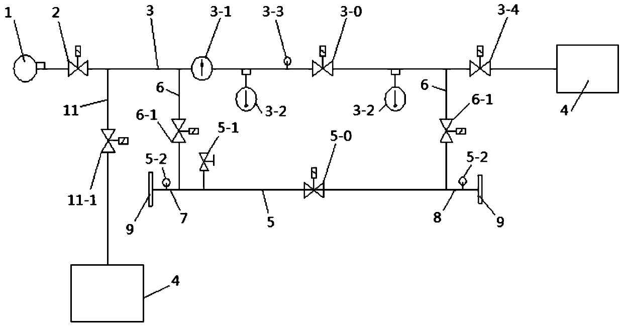
[0032] Such as figure 1 As shown, the test system of this embodiment is formed by connecting a working pump 1, a test main pipeline 3, a test branch pipeline 5 and related valves, wherein:

[0033] The inlet of the test main pipeline 3 is connected to the working pump 1, and the outlet is provided with a reservoir 4. The inlet and outlet of the test branch pipeline 5 are respectively connected to the main pipeline through the connecting pipeline 6, and the inlet of the test branch pipeline is also connected to the ball pipeline. 7. The outlet is connected with a ball receiving pipeline 8. At the same time, the inlet of the serving pipeline 7 and the outlet of the ball receiving pipeline 8 are respectively equipped with switchable mechanisms, specifically a quick-opening blind plate 9;

[0034] A pump outlet regulating valve 2 is installed at the outlet of the working pump; the first test valve installation position 3-0 is installed on the main test pipeline 3, and a flow meter...

Embodiment 2

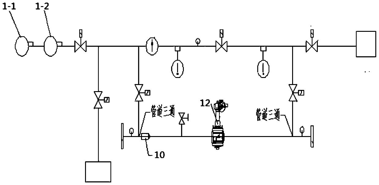
[0041] Another concrete test example, such as figure 2 As shown, the tested valve is the pigging ball valve 12, installed in figure 1 The 5-0 position is shown, and at the same time, the manual valve is installed at the 3-0 position; after that, the reliability of the ball passing through the pigging ball valve 12 under specified working conditions is tested, which can also be used to evaluate the impurity resistance of the pigging ball valve.

[0042] In this test example, combined with figure 1 and 2 As shown, the connecting pipeline of the service pipe, the inlet of the test branch pipeline and the corresponding end are connected through a pipe tee, and the ball collection pipeline, the outlet of the test branch pipeline and the connecting pipeline of the corresponding end are also connected through a pipe tee. The outlet of the ball pipeline is equipped with a quick-opening blind plate, and a pipe pig 10 is placed in the ball pipeline 7 and the ball collection pipeline ...


PUM


Abstract

The invention discloses a valve load test system. The test system comprises a working pump, a test main pipeline and test branch pipelines; an inlet of the main pipeline is connected with the workingpump; inlets and outlets of the test branch pipelines are respectively connected with the test main pipeline through connecting pipelines, and valves are mounted on the connecting pipelines; an inletof each test branch pipeline is further connected with a ball serving pipeline, and an outlet of the test branch pipeline is further connected with a ball receiving pipeline; and switchable mechanismsare installed at the inlet of each ball serving pipeline and the outlet of each ball receiving pipeline. According to the test system, a pressure source module, the main test pipeline and the test branch pipelines are designed, and various loads of the valve can be flexibly tested; and by adopting the test system provided by the invention, assessment tests of safety valves such as a switch valve,a regulating valve and a water hammer pressure release valve and various oil pipeline valves such as a pigging ball valve under different working conditions can be completed.

Description


Claims


Application Information

Patent Timeline
Owner CHINA PETROLEUM & CHEM CORP
Why Eureka
Try Eureka