Temple rod cam for supporting glasses
A temple, cam technology, applied in glasses/goggles, optics, instruments, etc., can solve problems such as redness, sunken, nose discomfort, etc.
Pending Publication Date: 2020-07-17
李广林
0 Cites 0 Cited by
AI-Extracted Technical Summary
Problems solved by technology
Still, glasses can add at least a few ounces to the nose, and regular glasses wearers have ...
Method used
[0045] In the preferred case, the temple rod cam 100 is made of silicone rubber, which has high elasticity, so that the temple rod cam 100 can deform during use as described below, and return to its original shape a...
Abstract
The temple rod cams for supporting the glasses are arranged on the temple rods on the left side and the right side of the glasses respectively, and temple rod receivers allowing the temple rods to penetrate through are arranged on the temple rod cams; a cam flap is arranged on one side, close to the face, of the temple rod cam; and the temple rod cam is supported by the face of a user and supportsthe glasses. When used in pairs for supporting a pair of glasses, the nasal septum of the glasses is kept above the nose of a wearer; when the glasses are worn on the face of a wearer, the temple rodcams can rotate to temples of the wearer, so that the glasses stop moving downwards, and the glasses are fixed to the position above the nose of the wearer.
Application Domain
Non-optical parts
Technology Topic
EngineeringStructural engineering +3
Image
Examples
- Experimental program(1)
Example Embodiment
[0042] The present invention will be further described now in conjunction with accompanying drawing.
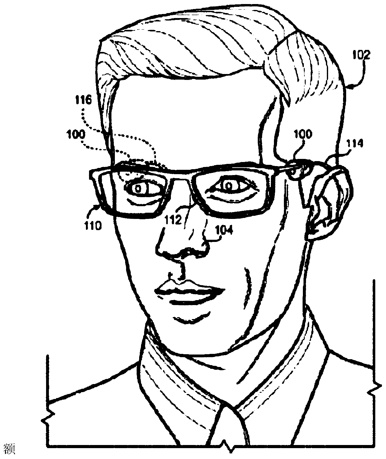
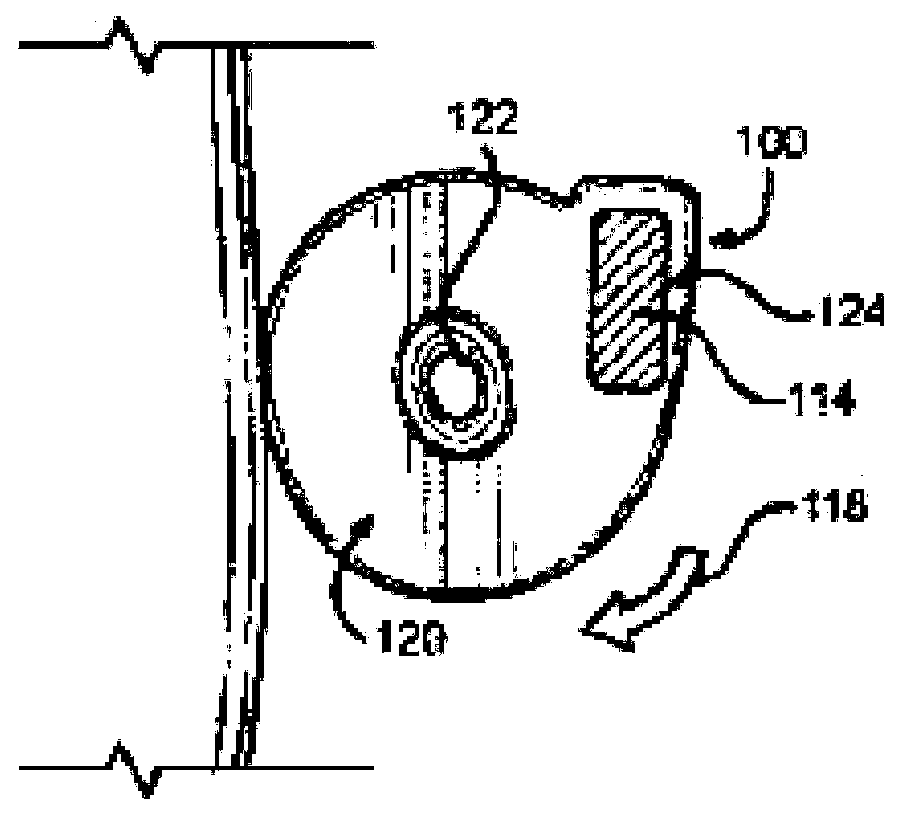
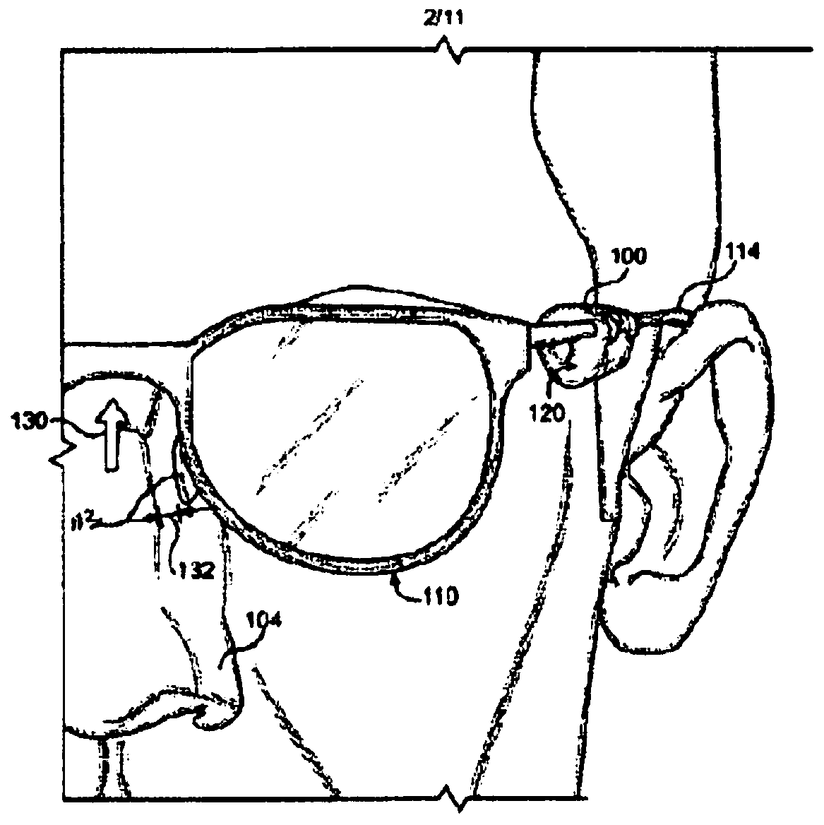
[0043] see first figure 1 , shows a pair of temple rod cams 100 in use. A wearer (user) 102 of glasses is wearing glasses 110 . Although eyeglasses 110 are shown to demonstrate the operation of temple stem cam 100, eyeglasses 110 are representative and temple stem cams may be used with other eyewear of similar construction, such as 3D glasses, goggles, color correcting glasses, plano glasses and other similar instruments. The glasses 110 include a nose bridge 112 that is generally supported by the nose 104 of the user 102 such that the majority of the weight of the glasses 110 rests on the nose 104 of the user 102 . However, a temple rod cam 110 is attached to the left temple rod 114 and the right temple rod 116 each. Each temple bar cam 100 is supported by the user's 102 face, holding up the eyeglasses 110 so that no weight is added to the nose 104 . Since a pair of glasses has two temple bars, two sun
[0044] Hole rod cams 100 are used at the same time, and it is normal for one temple rod to be equipped with one cam.
[0045] In a preferred case, the temple rod cam 100 is made of silicone rubber, which has high elasticity, so that the temple rod cam 100 can be deformed as described below during use, and return to its original shape after use. In the first case, the silicone rubber used is medical-grade silicone, so that it will not cause discomfort or adverse reactions to the skin of the user 102 that touches the temple rod cam 100 during use.
[0046] now refer to figure 2 , which is described using a temple rod 100 . The temple rod cam 100 is attached to the temple rod 114 on the left side of the glasses 110 (as figure 1 shown). Broadly speaking, the temple stem cam 100 is a deformable body having a temple stem receiver 124 sized to receive the temple stem 114 of a pair of eyeglasses 110 . When the temple rod 114 on the left side passes through the temple rod receiver 124, the main body deforms to form cam lobes 142 and 144 adjacent to the temple rod receiver 124 (as Figure 4 described). The temple bar cam 100 on the right temple bar 116 along the right side of the face of the user 102 serves a similar purpose and is therefore not separately described. Once so deformed, the remainder of the body assumes the shape of the cam lobe 120 relative to the temple rod receiver 124 .
[0047]When the glasses 110 are placed on the user's face, because the glasses 110 are connected to the user's ears and relatively lower than the user's nose, the temple rod cam 100 slightly higher than the nose 104 rotates and deforms in the direction 118 . Rotation of the glasses 110 toward the user's nose causes the cam lobe 120 of the temple stem cam 100 to contact one side of the user's face and compress in the rotational direction 118 until the temple stem cam 100 secures the glasses 110 on the user's temple. The conical hole 122 in the temple rod cam 100 allows the temple rod cam 100 to deform sufficiently so that the temple rod cam 100 can rest comfortably between the left temple rod 114 and the face of the user 102 .
[0048] see image 3 , the temple rod 114 on the left side and the face of the user 102 continue to generate pressure on the temple rod cam 100, and the temple rod cam 100 is fixed, which in turn holds the glasses 110 on the nose 104 of the user 102, as indicated by arrow 130 shown. This creates a small gap 132 between the bridge 112 and the nose 104 of the user 102 . Thus, the nose bridge 112 does not exert pressure on the nose 104 of the user 102, nor does it cause irritation, redness, or depression in the nose.
[0049] see Figure 4 , when the 110 pair of glasses is worn, between the left temple rod 114 and the face of the user 102, where the cam lobe 120 draws, the temple rod cam 100 moves in the direction shown by the arrow 140. Thus, the glasses 110 are fixed where they should be. exist Figure 4 Also visible in is the cam lobes 142 and 144, which consist of partial protrusions of the temple shaft cam 100. As the temple rod passes the temple rod receiver 124, cam lobes 142 and 144 are created.
[0050] now like Figure 5A As shown, when a temple rod, such as the left temple rod 114, passes through the temple rod receiver 124, the temple rod cam 100 assumes a cross-sectional shape with a circular appearance having a tail where the temple rod 114 passes. tail corresponds to Figure 4 Cam lobes 142 and 144 shown in . The rest of the circular portion of the temple rod cam 100 explains that the cam lobe 120 acts to stop the downward movement of a pair of 110 glasses (as in figure 1 shown).
[0051] like Figure 5B As shown, once glasses 110 (such as figure 1 ) is placed on the user's 102 face, and the glasses 110 begin to lower to their resting position, contacting the user's temples 102 and the cam lobes 120 of the temple rods cause the cam lobes 120 to rotate inwardly toward the face. The resiliency of the temple rod cam 100 facilitates internal rotational movement, which allows it to deform in shape as the temple rod 114 continues to move downward.
[0052] like Figure 5C As shown, the temple rod 114 is ultimately positioned to the side of the cam lobe 120 , opposite the face of the user 102 due to the deformation of the temple rod cam shape. The shape of the cam lobe 120 is deformed from the original circular shape, which is achieved by the elasticity of the temple rod cam 100 and the existence of the conical hole 122 to avoid discomfort to the user 102 . At this point, the rotational movement and deformation of the cam lobe 120 stops, and the temple rod 114 no longer moves downwards, but it is held in place by the temple rod cam 100 .
[0053] now as Image 6 As shown, on the upper or "top" of the base 150 (as in Figure 8 shown) is smaller in diameter than the base lower portion or "bottom" 152 (as Figure 7 shown), the preferred case of the temple rod cam 100 has a tapered funnel shape, and a circular cross section instead of a temple rod. This conical funnel shape ensures contact between the temple rod cam 100 and the temple of the user 102 along the entire length of the temple rod cam 100 . The conical bore 122 and temple rod receiver 124 extend from top 150 to bottom 152 and, in some cases, form part of the injection molding process of temple rod cam 100 manufacture, while in other cases, in the initial conical funnel shape. After production, they are cut into temple rod cams 100.
[0054] In addition to the tapered bore 122 and the temple rod receiver 124, an aperture 154 extends from the side surface 156 to the temple rod receiver 124 in the preferred case. In a preferred case, the aperture 154 has a rectangular shape, but other shapes may be used without departing from the invention. The presence of aperture 154 forms two stripes 154A and 154B (eg Figure 11 shown), the two strips are elastic and can be placed on temple bars. The described apertures allow for easier entry of the temple rod into the temple rod receiver 124 of the temple cam 100 .
[0055] now refer to Figure 7 , which illustrates the Image 6 Bottom view of temple rod cam 100 of FIG. 100 , showing bottom 152 , conical bore 122 and temple rod receiver 124 . like Figure 7 As shown, the conical bore 122 is also conical in shape in the preferred case, with its narrow end at the top 150 of the temple rod cam 100 (as shown in Figure 8 ), the wide end is located at the bottom 152 of the temple rod cam 100.
[0056] now refer to Figure 8 , which illustrates the Image 6 The right side view of the temple bar cam 100 of FIG. 10 shows the tapering of the side 156 from the bottom 152 to the top 150. The conical bore 122 is not visible from this angle, but is shown with a dotted line, and it can also be seen that the temple rod cam 100 gradually animates from the bottom 152 to the top 150, while in the preferred case the temple rod receiver 124 maintains its position throughout. The diameter does not change.
[0057] In order to use the temple rod cam 100, a temple rod of the glasses 110 (such as figure 1 Shown) is through the temple rod receiver 124, enters the bottom 152, and exits the top 150, so that when the glasses 110 are worn, the bottom 152 is facing the front of the user's 102 face (as shown in FIG. figure 1 ).
[0058] now refer to Figure 9 ,Shows Image 6 A front view of the temple rod cam 100 of FIG. 10 , showing the rectangular aperture 154. with conical bore 122 and temple rod receiver 124 (such as Figure 7 As shown), aperture 154 does not extend from bottom 152 to top 150; instead, it is substantially centered between bottom 152 and top 150. This forms cam lobes 142 and 144 (as Figure 4 shown), the sides 156 above and below the rectangular aperture 154 (as Figure 7 shown) part
[0059] Pushed outward as it passes the temple rod receiver 124 .
[0060] now refer to Figure 10 ,Shows Image 6 Rear view of the Temple Rod Cam 100. The rectangular aperture 154 is shown in phantom because it only extends to the temple rod receiver 124 (eg Figure 7 shown), so it cannot be seen from the opposite side of the temple rod cam 100.
[0061] now refer to Figure 11 ,Shows Image 6 An upper front perspective view of the temple rod cam 100 of FIG. Here, the frusto-conical shape of the temple rod cam 100 can be clearly seen, whereas the frusto-conical shape of the conical bore 122 is shown in dotted lines. On the other hand, the temple rod receiving 124 is cylindrical in shape. More specifically, in the preferred case, temple rod receiver 124 is a slanted cylinder maintaining a constant distance between the center of its cross-sectional circle and the nearest edge of side 156 . exist Figure 11 The top 150 can be seen in , showing the upper opening of the conical bore 122 and the temple rod receiver 124, which are approximately the same size.
[0062] now refer to Figure 12 ,shown Image 6 A lower rear view of the Temple Rod Cam 100. The bottom 152 is visible as the hole under the tapered hole 122 and the temple rod receiver 124 . As can be seen from the figure, the lower hole of the conical bore 122 is significantly larger than the lower hole of the temple rod receiver 124 due to its truncated cone shape.
[0063] now refer to Figure 13 to Figure 24 , alternative cases of temple rod cams have different shapes, which make the temple rod cams vary in varying degrees in how easily and how easily the shape deforms. Both the deformable nature and the shape itself cause the temple rod cam to rest against the user's face in different ways. Therefore, certain consumers may prefer certain cases over others.
[0064] now refer to Figure 13 , shows an alternative case of a temple rod cam, usually specified as 200. The temple stem cam 200 has a substantially cylindrical cam lobe 220 with a cylindrical hole 222 passing through its center. A temple rod receiver 224 with oval cross-section creates a protrusion from the cylindrical shape of the cam lobe 220 . The front face 250 of the temple rod cam 200 is substantially similar in appearance to its reverse face (not shown), with both the cylindrical aperture 222 and the temple rod receiver 224 extending from the front face 250 to the reverse face. The aperture 254 on the side 256 of the temple stem cam 200 sits on the protrusion and extends to the interior of the temple stem receiver 224 .
[0065] now refer to Figure 14 , the temple rod cam 200 is the temple rod 110 that places a pair of eyeglasses through the temple rod receiver 224 . In other cases, when the user wears the glasses, the cam flap 220 (eg Figure 13 shown) press against one side of the user's face to prevent the glasses from resting on the user's nose.
[0066] now refer to Figure 15 , shows an alternative case of a temple rod cam, usually specified as 300. The cam lobe 320 of the temple rod cam 300 does not have a hole passing through it, but the hook or beak shape of the cam lobe 320 provides a concave surface, which provides a similar conical hole 122 to the temple rod cam 200 (as shown in FIG. figure 2 shown), and a cylindrical hole 222 is provided for the temple rod cam 200 (as Figure 13 ) flexibility. The temple rod receiver 324 is located at the beak protrusion from the cam lobe 320 and, as in the other cases, is a hole extending from the top surface 350 of the temple rod cam 300 to the bottom surface (not shown). The temple bar cam 300 also has a side 356 .
[0067] now refer to Figure 16 , the temple stem cam 300 is used by placing the temple stem of a pair of eyeglasses 110 into the temple stem receiver 324. In other cases, when the user wears the glasses, the cam lobe 320 presses against one side of the user's face, preventing the glasses from resting on the user's nose.
[0068] now refer to Figure 17 , shows an alternative case of a temple rod cam, usually specified as 400. In the temple stem cam 400, a cam lobe 420 protrudes from a temple stem receiver 424 in a C-shape. The front side 450 and the substantially similar back side form a C-shaped cross-section, surrounded by sides 456 . As with the other cases, the temple rod receiver 424 extends from the front side 450 to the back side (not shown) through the temple rod cam 400 . The concave inner surface of the C-shaped cam lobe 420 provides a degree of flexibility for deformation of the temple rod cam 400 in use.
[0069]now refer to Figure 18 , the temple rod cam 400 is used by placing the temple rod of a pair of eyeglasses 110 into the temple rod receiver 424. In other cases, when the user wears the glasses, the cam lobe 420 presses against one side of the user's face, preventing the glasses from resting on the user's nose.
[0070] now refer to Figure 19 , shows an alternative case of a temple rod cam, usually specified as 500. The temple rod cam 500 is L-shaped. The letter "L" is composed of a vertical line segment (or "stem") and a horizontal line segment (or
[0071] "legs"), perpendicular to the stem, extending from the bottom end of the stem to the right. The legs are almost always shorter in length than the stem, and the corresponding part of the temple stem cam 500 is no exception. exist Figure 19 , the temple stem cam 500 is shown horizontal to the valve stem, as if the "L" had been rotated 90° clockwise. The end of the stem, the end of the leg, and the intersection of the stem and leg are all round. There is a concave edge between the intersection and the end of the legs. The hole 522 is located at the end of the valve stem, while the temple stem receiver 524 is located at the end of the leg. Both the aperture 522 and the temple rod receiver 524 extend from the front side 550 to the back side of the temple rod cam 500 . Sides 556 extend along the perimeter of the L-shape.
[0072] In the temple rod cam 500, the aperture 522 is shaped similarly to the temple rod receiver 524, which allows some flexibility to the user as the roles of the aperture 522 and the temple rod receiver 524 can be interchanged. More particularly, depending on the user's preference, the user may choose to place a temple rod in the aperture 522 instead of placing a temple rod in the temple rod receiver 524, giving the user greater flexibility when using the temple rod cam 500. Bring different feelings.
[0073] now refer to Figure 20 , the temple rod cam 500 is a temple rod that fits into a pair of eyeglasses 110 at the temple rod receiver 524 . Alternatively, temple rods may pass through aperture 522 . In other cases, when the user wears the glasses, the cam lobes press against one side of the user's face, preventing the glasses from resting on the user's nose. When the temple rod passes through the temple rod receiver 524, the legs act like cam lobes. However, when the temple stem passes through the aperture 522, the valve stem can act as a cam lobe. In other cases, when the user wears the glasses, the cam lobes press against one side of the user's face, preventing the glasses from resting on the user's nose.
[0074] now refer to Figure 21 , showing an alternative case of a temple rod cam, usually specified as 600. The temple rod cam 600 has a long, slightly curved cam lobe 620. The temple rod receiver 624 extends from the front side 650 to the back side of the temple rod cam 600 . Side 656 surrounds the perimeter (not shown) of temple bar cam 600 between front side 650 and back side.
[0075] now refer to Figure 22 , the temple rod cam 600 is used to place the temple rod of a pair of eyeglasses 110 in the temple rod receiver 624. In other cases, when the user wears the glasses, the cam lobe 620 presses against the side of the user's face, preventing the glasses from resting on the user's nose.
[0076] now refer to Figure 23 , showing an alternative case of a temple rod cam, usually designated 700. The temple rod cam 700 has a shoe-shaped cross-section with two apertures 722A and 722B on the cam lobe 720 forming the main body of the shoe, and the temple rod receiver 724 is in the shoe. Apertures 722A, 722B and temple rod receiver 724 extend from front face 750 to the reverse face of temple rod cam 700 . Sides 756 surround the perimeter of the shoe shape.
[0077] now refer to Figure 24 , the temple rod cam 700 is used by placing the temple rod of a pair of eyeglasses 110 in the temple rod receiver 724. In other cases, when the user wears the glasses, the cam lobe 720 presses against the side of the user's face, preventing the glasses from resting on the user's nose.
[0078] The embodiments of the present invention have been described above in conjunction with the accompanying drawings and the examples. The structures given in the examples do not constitute limitations to the present invention. Those skilled in the art can make adjustments as needed, within the scope of the appended claims All kinds of deformation or modification are within the scope of protection.
PUM


Description & Claims & Application Information
We can also present the details of the Description, Claims and Application information to help users get a comprehensive understanding of the technical details of the patent, such as background art, summary of invention, brief description of drawings, description of embodiments, and other original content. On the other hand, users can also determine the specific scope of protection of the technology through the list of claims; as well as understand the changes in the life cycle of the technology with the presentation of the patent timeline. Login to view more.