Supercharge Your Innovation With Domain-Expert AI Agents!

High-coupling air-core split reactor

A split reactor and high-coupling technology, which is applied in signal inductors without magnetic cores, transformer/inductor coils/windings/connections, circuits, etc., can solve problems such as large insulation distances and reduce the coupling coefficient of two sets of coils , to achieve the effect of resolving the contradiction

Pending Publication Date: 2020-07-17
辽宁芯峻电气有限公司
View PDF0 Cites 0 Cited by
  • Summary
  • Abstract
  • Description
  • Claims
  • Application Information

AI Technical Summary

Problems solved by technology

Therefore, when making an air-core reactor, a large insulation distance is required between the two sets of coils, but when the insulation distance is increased, the coupling coefficient of the two sets of coils will be reduced, so the technical problem of the dilemma has not been resolved.

Method used


Image

  • High-coupling air-core split reactor
  • High-coupling air-core split reactor
  • High-coupling air-core split reactor

Examples


Embodiment 1

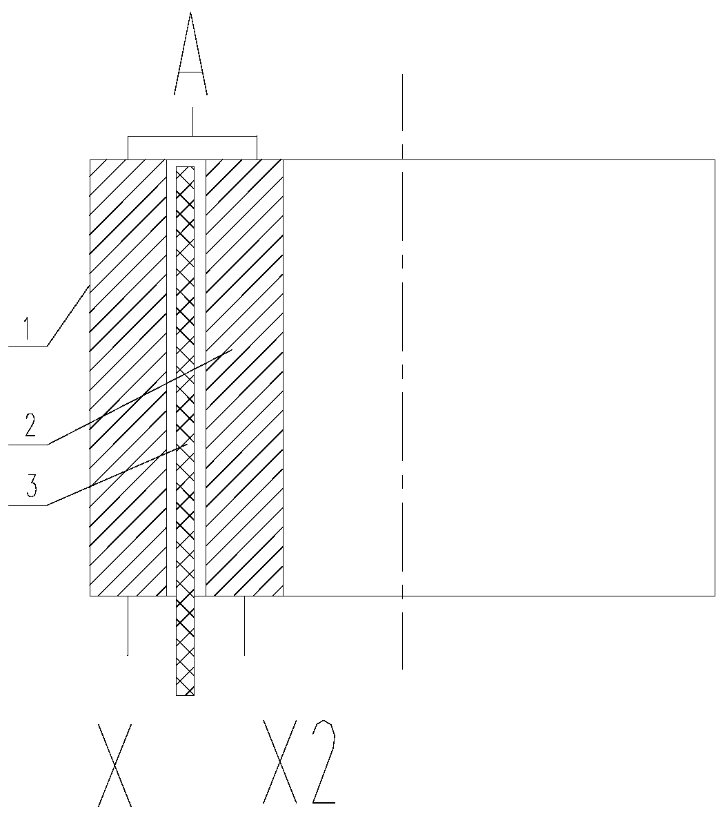
[0016] refer to image 3 , Figure 4 with Figure 5 , this embodiment provides a high-coupling air-core split reactor, including a cylindrical first winding 1 and a second winding 2 whose outer diameter is smaller than the inner diameter of the first winding 1, and the first winding 1 and the second winding 2 are concentrically socketed A cylindrical insulating barrier 3 is provided between the first winding 1 and the second winding 2, the lower end of the cylindrical insulating barrier 3 is longer than the first winding 1 and the second winding 2, and the upper ends of the first winding 1 and the second winding 2 are common The lower end of the first winding 1 and the second winding 2 is a split outlet end; there is an incoming terminal block 4 and the upper part of the first winding 1, the second winding 2 and the insulation barrier 3 Connection, the first outgoing terminal row 5 is connected to the lower part of the first winding 1, the second outgoing terminal row 6 is c...


PUM


Abstract

The invention belongs to the technical field of air core split reactors, and particularly provides a high-coupling air-core split reactor. The transformer comprises a cylindrical first winding and a second winding with the outer diameter smaller than the inner diameter of the first winding. Wherein the first winding and the second winding are concentrically sleeved, a cylindrical insulating barrier is arranged between the first winding and the second winding, the lower end of the cylindrical insulating barrier is longer than the first winding and the second winding, the upper ends of the firstwinding and the second winding are common wire inlet ends, and the lower ends of the first winding and the second winding are split wire outlet ends. Through the arrangement of the cylindrical insulation barrier, the contradiction between the insulation and the coupling coefficient of the air core split reactor is solved.

Description

technical field [0001] The invention belongs to the technical field of air-core split reactors, and specifically provides a high-coupling air-core split reactor. Background technique [0002] High-coupling air-core split reactors can be used to limit short-circuit current, the principle is as follows figure 1 , when the line is running normally, K is closed, at this time L1 and L2 are connected in antiparallel, the magnetic field cancels, and the overall inductance is small; when the circuit is short-circuited, K is broken, and only L1 is running. At this time, the inductance is the inductance value of L1, which limits the short circuit Current, although the absence of current in L2 will not cancel the magnetic field, but the mutual inductance voltage of L2 still exists. There will be a terminal voltage equivalent to the line voltage at the outlet of the X terminal of the inductor L1 and L2. Considering the operating overvoltage of the inductor, the voltage here will be hig...

Claims


Application Information

Patent Timeline
Patent Type & Authority Applications(China)
IPC IPC(8): H01F27/32H01F27/29H01F17/02
CPCH01F27/323H01F27/29H01F17/02
Inventor 姚继宇贾继莹邱清泉张志丰蔡虹
Owner 辽宁芯峻电气有限公司
Features
  • R&D
  • Intellectual Property
  • Life Sciences
  • Materials
  • Tech Scout
  • Unparalleled Data Quality
  • Higher Quality Content
  • 60% Fewer Hallucinations
Learn More